
Space Time – Track Circuits with Trellis Code Modulation
Volume 2, Issue 3, Page No 1070-1079, 2017
Author’s Name: Marius Enulescua)
View Affiliations
Engineering & Design, Obrascon Huarte Lain, 1400- SKI, Norway
a)Author to whom correspondence should be addressed. E-mail: mariusenulescu@yahoo.com
Adv. Sci. Technol. Eng. Syst. J. 2(3), 1070-1079 (2017); ![]() DOI: 10.25046/aj0203136
DOI: 10.25046/aj0203136
Keywords: Track Circuit, Trellis coding, Space Time diversity

Export Citations
The track circuits are very important equipments used in the railway transportation system. Today these are used to send vital information, to the running train, in the same time with the integrity checking of the rail. The actual track circuits have a small problem due to the use of the same transmission medium by the signals containing vital information and the return traction current, the running track rails. But this small problem can produce big disturbances in the train circulation, especially in the rush hours.
To improve the data transmission to the train on-board equipment, the implementation of new track circuits using new communication technology were studied. This technology is used by the mobile and satellite communications and applies the principle of diversity encoding both time and space through the use of multiple transmission points of the track circuit signal for telegram which is sent to the train. Since this implementation does not satisfy the intended purpose, other modern communication principles such as 8PSK signals modulation and encoding using Trellis Coded Modulation were developed. This new track circuit aims to solve the problems which appeared in the current operation of track circuits and theoretically manages to transmit vital information to the train on board equipment without being affected by disturbances in electric traction transport systems.
Received: 29 April 2017, Accepted: 14 June 2017, Published Online: 15 July 2017
1. Introduction
In the paper [1] “Track circuit with space-time coding” it has been shown that the present track circuits used in metro lines have some problems, connected with the train transmission telegrams due the electrical perturbation produced by the train return current. To have one conclusion about this problem, at the Bucharest Metro line, measurements were taken and oscillograms picked-up, for more than 100 track circuits. These measurements were conducted to find the real cause of the sudden emergency brakes applied by the running metro trains. The trains lose the command telegram for a while and apply the brakes for safety reasons. The telegram contains the permissive orders to run regarding the permissive speed and distance to go. These emergency brakes lead to disturbances in the train time schedule and jeopardize the passengers’ safety. To solve this problem, several solutions have been proposed but none of them have been able to fully meet the proposed goal.
In paper [1] “Track circuit with space-time coding” an embodiment was proposed to be utilized, using the existing signalling equipment, to ensure the transmission of the telegrams to the train using two transmitter points at a fixed position from one another. The two telegrams emitted by tuning unitsTU1-a and TU1-b arrive to the train at a time interval δ one after the other. This interval enables the rapid verification of the telegrams if they contain errors and if they do, the receiver can correct them.
The disadvantage of the embodiment is that on the distance between the two transmitters TU1-a and TU1-b, the train receives only the second telegram, leading to the need of a geographical map at the on board receiver and the verification of the position of the train if it is found between the TU units. But the main disadvantage is the use of additional equipment which has a high cost, namely one TU unit for each track circuit.
The train receives orders that authorize its movement entire in full safety conditions. The orders are embedded in a telegram that is transmitted through the track rails. The telegram addressed to the train can be disrupted and the train cannot recognize the transmitted order. And this fact leads on the train to apply the emergency brake [2].
The QPSK-MIMO track circuit proposed in previous works cannot provide telegram transmission during the window time requested by the receiver. The two telegrams required for MIMO diversity are composed of 8 bits needed to identify the track circuit, 29 bits of information, 1 utility bit, and 33 bits allocated for the verification of the telegram by CRC code totaling 72 bits per telegram [4]The telegram is affected while it passes through the communication channel via rails [3]. This channel is not a special channel built for data transmission. Because of this, the telegrams are affected by the return traction current and electrical noise produced by the electrical motors of the train. In this paper such issues are analyzed and a new solution is proposed to solve the telegram loss by the train, when the telegram is affected by disturbances similar to Dirac impulses.
For the transmission of the two telegrams in the window time allocated by the receiver for the reception of a telegram, namely 630 ms [5], one should be reduced the bit time by way of changing the oscillators in the existing receivers, which does not correspond with the scope to improve the current system with minimum changes. The second method of shortening the transmission time of the telegram is to decrease the length of the transmitted telegram. In order to reduce the transmitted telegram, the only option is to drop the CRC code and replace it with another encryption and error protection system. In order to transmit the 38-bit utility telegram it is needed to look for a coding to allow the telegram to be checked and the transmission to be carried out in less than 315 ms even below 300 ms, because 15 ms should be allocated to the time between the two telegrams.
| Information format |
| Encryption |
| Coding |
| MUX |
| Modulator |
| Filter |
| Transmitter |
| Transmission Chanel |
| Receiver |
| Demodulator |
| Filter |
| DEMUX |
| Decoding |
| Decryption |
| Information decoding |
| Information |
| Message symbols |
| Other messages suppliers |
| Chanel symbols |
| Transmitter |
| Receiver |
| Information |
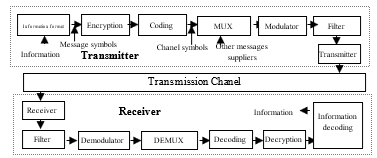 Figure 1. Transmission of information in communication systems
In the previous works have been implemented the transmission technologies used by today’s WIFI communications systems so far, in this paper is proposed to try to use Trellis encoding. Trellis encoding is a coding commonly used in current communication systems. The transmission of the telegram in the current system is performed by transmitting the information in 30-bit information blocks which are accompanied by a 33-bit CRC block. If an informational bit is affected at the moment of reception, when performing the polynomial division modulo two, the result is not identical to that of the CRC code, and the telegram is declared disrupted. If a convolution code is used then information bits and control bits are combined into a set structure, practically decoding is bitwise with a continuous bit and if a bit is disturbed then it is not considered to be the entire lost word. In the classical data transmission systems functional blocks appear as in Figure 1. In a communication system two main functional blocks can be distinguished, namely the transmitter and the receiver. The main functionality blocks are: „information formatting block” – it collects the information that is the subject of the transmission and processes it by obtaining the message symbols and then these messages enter into the „encryption block” to ensure data protection.
The message is coded [6] to be transmitted through the communication channel in order to obtain the channel-specific symbols, the „multiplexing block” which allows the access to the transmission channel of several message sources. The received messages are modulated and passed through a „band pass filter” that only allows the passage of useful frequencies to the „broadcasting block”. The „broadcast block” amplifies and does the adaptations with the „data transmission channel” towards the reception. At the „reception”, the information is extracted by the reverse execution of the operations performed in the „broadcasting block”. If a more efficient system is desired, the complexity of the system must be increased, with the advantages and disadvantages of the solution. Increasing the system performance can be done by using Trellis Coded Modulation (TCM). The use of Trellis coding performs coding and modulation of the signal in the same block, which reduces the time required for data processing, but at the same time requires specialized electronic components made by state-of-the-art techniques, allowing complicated operations. Trellis encoded data transmission systems have very good noise protection and are used for high-speed data transmissions. In the case of a limited power communication channel, increasing energy efficiency can be achieved by using error correction codes. Corrector error codes supplement additional bits to the transmitted encoded information sequence. Adding supplementary bits to the useful information results in the need for longer words to be transmitted, and if they need to be received in a given window time, it is necessary for the modulator to work at a higher frequency requiring a wider frequency band. The maximum data transmission speed through an ideal communication channel (stable, homogeneous, invariant in time, without distortion) is limited. This limit, called the capacity of the communication channel C [bit / s], was established by Shannon for an ideal channel with add-on Gaussian white noise, with a mean power of the useful signal and assuming the infinite coding, as to be:
C= B log2 (1 +P/ N) [bit/s] (1)
Where the capacity of the communication channel is denoted by C and B is the bandwidth available for communication, the average signal power is P and the average noise power is N. In the case of a limited frequency band communication channel, increasing the spectral efficiency can be achieved by using modulators that maintain a large distance between the signals. These modulator processes are based on Shannon’s 2nd theorem: a source with the information flow R (bit / s) and a channel with capacity C (bit / s) and if R <C then there is a code with words of length „n” such that the probability of a decoding error Pe to be Pe≤ 2-nE (R) where E (R) is a non-negative function called the exponent errors – the theorem allege that indifferent how much the channel transmission is disturbed, the broadcast can be made with a minimal error probability. The sequence error probability (as well as the probability of symbol error) is limited up by a decreasing function ratio d min2 / N0 and is well approximated by this expression when the signal / noise ratio is high. In the above expression dmin2 is the square of the minimum Euclidean distance between two possible signal vector sequences. The Euclidean distance is a straight line between two points “s1” and “s2“, each point is defined by the Cartesian coordinates (2). The distance between the two symbols is given by the relationship.
![]() For digital transmission, the equivalent of the Euclidean distance is the Hamming distance given by the relation (3), this is zero if the binary words are the same. These two distances are useful in signals processing.
For digital transmission, the equivalent of the Euclidean distance is the Hamming distance given by the relation (3), this is zero if the binary words are the same. These two distances are useful in signals processing.
dH(x,y)= ; dH(x,y)= (3)
For an optimal communication, a long sequence of signals with maximum separation must be transmitted, and the receiver must decide on these long signals rather than individual bits or symbols.
If the designing process of these long signal sequences is properly performed, the error probability of the message „ve” decreases exponentially with the length n.
![]() Where the transmission rate R is less than the maximum rate R0 as given by the Shannon capacity of the channel. In conventional transmission, encoding is separate from the signal modulation operation. Coding is done at the digital level, this in generally adds bits to the streams to be transmitted and requires an increased bandwidth. At the receiver the decoding occurs after the signal demodulation. The demodulation can be done by electronic circuits for decision, with voltage thresholds, and is called „hard demodulation” or can be done by sampling the received signal and comparing these samples with memorized patterns of the signal accompanied by Gaussian noise, this is a „soft demodulation”. “Soft demodulation” brings a 2 dB gain compared to „hard demodulation”. The decoding operation is executed for the entire data stream that feeds the decoder, whether it contains an error or not. Decoding can be done by sampling the received analogue signals and comparing them with memorized patterns, this is a comparative decoding. The theoretical loss of the decoder by electronic decision over the comparative decision is about 2 dB. Modulation of coded signals can be a 2D modulation, which uses the dependence between the initial phase and the phase of the quadratic symbols. It is manageable to have a 4D modulation; where it introduces the dependence of the symbols of two successive time intervals. A Trellis modulation can be used, that introduces the dependence of each successive symbol. Trellis and multidimensional codes are designed to maximize the Euclidean distance between the possible sequences of the transmitted symbols. The distance between the nearest possible symbols transmitted in the signal space determines the performance of the code Pc where dmin is the minimum distance between the signal sequences and N is the noise power in the channel. Trellis Coded Modulation combines modulation and encoding in the same block, while the bandwidth is not increased. It has the same symbol rate, but redundancy is introduced by using to encode a constellation with more points, than it would be needed without encoding. For Trellis Coded Modulation the number of point doubles but the symbol rate is the same and the spectral power remains the same. Since there are several possible points per symbol, it can be considered that for a given noise signal ratio the probability of error increases. As with the conventional coding, there is a dependency between different symbols. Only certain secure sequences for successive points of the signal constellation are allowed for Trellis encoding. By applying these constraints optimally at the reception, the probability of error decreases, as a measure of the transmission performance while growth the coding gain. This is the difference between the transmission through a channel with the same noise to signal ratio of the same information in a coded system and a non-coded system. The key element of Trellis Coded Modulation, to improve the power efficiency of a coded channel, is to insert a memory circuit. To compensate the redundant bits added at the signal encoding, a constellation with more than 2n symbols is used. The design of the encoder and the constellation map is collaborated to reduce the complexity of the decoder. Using an 8-layer constellation for signal encoding, theoretically 2 bits per symbol can be transmitted with an error below 13dB. Using a coded modulation it is possible get a 6dB gain at the same symbol rate without increasing bandwidth [7]
Where the transmission rate R is less than the maximum rate R0 as given by the Shannon capacity of the channel. In conventional transmission, encoding is separate from the signal modulation operation. Coding is done at the digital level, this in generally adds bits to the streams to be transmitted and requires an increased bandwidth. At the receiver the decoding occurs after the signal demodulation. The demodulation can be done by electronic circuits for decision, with voltage thresholds, and is called „hard demodulation” or can be done by sampling the received signal and comparing these samples with memorized patterns of the signal accompanied by Gaussian noise, this is a „soft demodulation”. “Soft demodulation” brings a 2 dB gain compared to „hard demodulation”. The decoding operation is executed for the entire data stream that feeds the decoder, whether it contains an error or not. Decoding can be done by sampling the received analogue signals and comparing them with memorized patterns, this is a comparative decoding. The theoretical loss of the decoder by electronic decision over the comparative decision is about 2 dB. Modulation of coded signals can be a 2D modulation, which uses the dependence between the initial phase and the phase of the quadratic symbols. It is manageable to have a 4D modulation; where it introduces the dependence of the symbols of two successive time intervals. A Trellis modulation can be used, that introduces the dependence of each successive symbol. Trellis and multidimensional codes are designed to maximize the Euclidean distance between the possible sequences of the transmitted symbols. The distance between the nearest possible symbols transmitted in the signal space determines the performance of the code Pc where dmin is the minimum distance between the signal sequences and N is the noise power in the channel. Trellis Coded Modulation combines modulation and encoding in the same block, while the bandwidth is not increased. It has the same symbol rate, but redundancy is introduced by using to encode a constellation with more points, than it would be needed without encoding. For Trellis Coded Modulation the number of point doubles but the symbol rate is the same and the spectral power remains the same. Since there are several possible points per symbol, it can be considered that for a given noise signal ratio the probability of error increases. As with the conventional coding, there is a dependency between different symbols. Only certain secure sequences for successive points of the signal constellation are allowed for Trellis encoding. By applying these constraints optimally at the reception, the probability of error decreases, as a measure of the transmission performance while growth the coding gain. This is the difference between the transmission through a channel with the same noise to signal ratio of the same information in a coded system and a non-coded system. The key element of Trellis Coded Modulation, to improve the power efficiency of a coded channel, is to insert a memory circuit. To compensate the redundant bits added at the signal encoding, a constellation with more than 2n symbols is used. The design of the encoder and the constellation map is collaborated to reduce the complexity of the decoder. Using an 8-layer constellation for signal encoding, theoretically 2 bits per symbol can be transmitted with an error below 13dB. Using a coded modulation it is possible get a 6dB gain at the same symbol rate without increasing bandwidth [7]
| 0.586 |
| 2 |
| 3.14 |
| 4 |
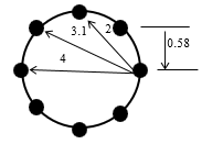 Figure 2. Euclidean distances for 8PSK
Trellis encoding, for a given limited channel bandwidth, at first, will be determined the rate of symbols that can be transmitted. The size of the 2L alphabet, which is required to produce the required bit rate, is determined. The constellation size is doubled and inserted into the encoder, which will generate an extra bit. It is not necessary that all the bits from the encoder input to be passed through the encoder. There are several ways to encode the bits in the symbols. The selected mapping can dramatically improve or dramatically reduce the code performance. Ungerboeck proposed a heuristic technique called mapping symbols, by partitioning symbol sets. The coding philosophy is to position the large constellation of 22L + 1 signals in smaller sets. The Euclidean distance between the signal point sequences in the different subsets is substantially increased (can be of the same order for all points in the same subset). Performance can be determined by the distance between symbol sequences in different subsets. Trellis encoding produces a substantial increase in the Euclidean distance between the signal sequence points so that at the receiver, the Viterbi algorithm can be used to detect the signal.
Ungeboeck in 1976 showed that for channels with bandwidth restricted by using convolution signal encoding, the gain of coding by comparison with binary encoding of the same signal can be substantially improved [8]. He proposed the use of modulation and coding together, to increase the Euclidean distance between the signal sequences. This was called Trellis encoding of the channel, because the sequence states in the finite state automaton that encode the signal levels describe a trajectory in the form of trellis for the possible passages. The largest Euclidean distance between the signal sequences, the lowest error rate for the noise signal ratio is Pe = NfreeQ (dfree/2Z) where Nfree is the mean of the sequence numbers at the distance dfree and Q (x) .
The code words consist of level sequences modulated. Trellis encoding uses dense signal sets but restricts what sequences can be used. These produce a minimum distance gain and the code requires a time dependence of the signal sequences that allow the receiver to pass over the noise bursts like the transmitted sequence estimates. Since the shape of the symbol and the transmission rate are unchanged, coding does not require any bandwidth increases.
This theory can be applied in track circuits for telegram transmissions to the train in FSK system, for which two symbols are used. To use a TCM for the order telegram, the FSK modulation signal can be used and, according to Ungerboeck’s rules, a dual-signal constellation with 4 frequencies is needed:
| f10 |
| f01 |
| f11 |
| f00 |
The frequency band is kept by setting the conditions:
f00-f10= f0-f1
and f00-f01=f01-f10=f01-f11
This requires a slightly more complicated receiver, but not so much. Indeed, the demodulator is a frequency-to-voltage converter: for example, for the frequency f0 at the output will have -U (volts) and for the frequency f1 the output will be + U (volts).
If there are 4 frequencies, the demodulator gives to the output for each frequency a preset voltage value as in the following example: For f00 the output will be -3U, for f11 is + 3U, for f01 is -U and for f10 output will be + U. The four-level signal ± U, ± 3U is easy the convert into di-bits (two-bit group). The four-frequency set is divided so that the minimum distance between two characteristic frequencies increase:
| {f00,f01,f10,f11} |
| {f00,f10} |
| {f01,f11} |
| {f00} |
| {f10} |
| {f01} |
| {f11} |
The new aspect of coded modulation Trellis is that the encoding and modulation operations are not treated as independent operations, but as a single operation. The signal received, instead of being first demodulated and then decoded, is processed by a receiver that combines demodulation and decoding in a single operation. The detection process involves more soft decisions than hard decisions (the incoming signal is processed before making the decision with which data source symbol it matches). To exemplify the operation, a convolution Trellis coder is used as in Figure 3
| T |
| + |
| T |
| σ 1(n+1) |
| σ 0(n+1) |
| σ 1(n) |
| σ 0(n) |
| δ0(n) |
| δ1(n) |
| b(n) |
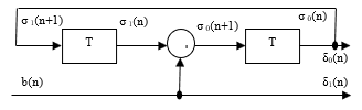 Figure 3. Transmission of information in convolution systems
The input bit bn goes unmodified at the exit and is renamed δ1(n), δ1(n)=bn
| + |
| σ0(n+1) =bn |
| σ1(n) |
The convolution encoder has 4 states, given by bits δ0(n) and δ1(n). These states are the outputs of some delay elements (bi-stable, tipping circuits) that use a tact T equal to the duration of one bit. For the coder shown in Figure 3:
δ0(n) = σ0(n)
σ1(n+1) = σ0(n) (5)
Table 1 Frequencies of signal issued to Trellis encoding
| δ1(n) | δ0(n) | frequency |
| 0 | 0 | f00 |
| 1 | 0 | f10 |
| 0 | 1 | f01 |
| 1 | 1 | f11 |
The two output bits δ0 (n) and δ1 (n) select the frequency of the transmitted signal as shown in Table 1:
The four-state Trellis graph which represents the operation of the convolution encoder is shown in Figure 4:
| σ1(n) |
| σ0(n) |
| σ1(n+1) |
| σ0(n+1) |
| 0 |
| 0 |
| 0 |
| 1 |
| 1 |
| 0 |
| 1 |
| 1 |
| 0 |
| 0 |
| 0 |
| 1 |
| 1 |
| 0 |
| 1 |
| 1 |
| 0100 |
| 1110 |
| 0100 |
| 1111 |
| 0101 |
| 1110 |
| 0101 |
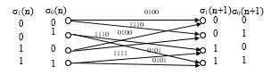 Figure 4. Four-State Trellis Graph
The convolution encoder state table, according to the previous states and the input data described above, is as follows:
Table 2 Trellis convolution coder states
| σ1(n) | σ0(n) | bn | σ1(n+1) | σ0(n+1) | δ1(n) | δ0(n) | frequency |
| 0 | 0 | 0 | 0 | 0 | 0 | 0 | f00 |
| 1 | 0 | 1 | 1 | 0 | f10 | ||
| 0 | 1 | 0 | 1 | 0 | 0 | 1 | f01 |
| 1 | 1 | 1 | 1 | 1 | f11 | ||
| 1 | 0 | 0 | 0 | 1 | 0 | 0 | f00 |
| 1 | 0 | 0 | 1 | 0 | f10 | ||
| 1 | 1 | 0 | 1 | 1 | 0 | 1 | f01 |
| 1 | 1 | 0 | 1 | 1 | f11 |
If the encoder state is “00” and the input bit is bn = “1”, the encoder switches to the state “01” and the transmitted frequency is f01. One advantage of the FSK modulation is that it does not need to equalize the transmission channel. For demodulation, the receiver uses only the input signal frequency, ignoring the amplitude and phase. For the above Trellis encoded scheme, the Viterbi algorithm can be used at reception. The algorithm was first proposed in 1967 and is an asymptomatic optimal decoding technique for convolution codes. It can be used to determine the encoded signal sequence close to the received signal sequence with the condition that the signal sequences transmitted are finite. The decoder determines the nearest signal sequence coded, directly from the information channel output. The most probable errors made by the decoder’s optimal soft decision are related to the Euclidean minimum distance of the transmitted symbols.
2. Trellis Track Circuit – functionality analysis
For the TI21M track circuit an informational telegram, consisting of 29 informational bits, shall be transmitted to the train. They are divided according to the table 3 [9, 10].
From the table 3, it can be seen that the new Trellis Track Circuit must send the following information: [11, 12]
– The target distance – bits 0-7, contains 8 informational bits to transmit the allowed distance whereon the train can travel.
– The target restriction – bits 8-10, contains 3 informational bits to convey the target restriction. This tells to the train if a speed restriction or a change in the type of traffic follows.
– Door left- bit 11, an informational bit to transmit to the train if left-handed doors are allowed.
– Door right – bit 12, an informational bit to transmit to the train if the right door is allowed to be opened.
– Entry into the controlled area- bit 13, an informational bit that informs the train if it enters or exits in the system-controlled area.
– Passing over- bit 17, an informational bit informing the train that an area, where the train can lose the telegram for a short distance, is coming.
– Current speed and target speed- bit 18-24, 7 informational bits informing about the train speed and target speed.
Table 3 Meaning of bits in the telegram transmitted by the TI21M track circuit
| bits | information |
| 0-7 | Target distance |
| 8-10 | Target restriction |
| 11 | Left doors |
| 12 | Right doors |
| 13 | Entrance in an controlled area |
| 14-16 | Track circuit markers |
| 17 | Over pass |
| 18-24 | Target and current speed |
| 25-28 | Target Gradient |
| 29 | Utility |
| 30-63 | CRC Cod |
In total there are 22 bits of information to be transmitted to the train. The rest of the information being transmitted, by the current track circuits, is linked to track circuit’s markers, which can be assimilated by the track circuit labelling. The CRC code bits can be removed, if another message verification method is used at the reception. The telegram that needs to be transmitted by the track to the train now has 30 informational bits.
If a Trellis encoding scheme is used, like the one shown in Figure 5.30, with a simple systematic feedback response coder and parity check, at two information bits from the encoder input it will have three bits at its output. This type of coding, with a ratio of 2/3, brings at the encoder output a 45-bit encoded trellis with parity check, where “hi ” are the parity coefficients.
For this scheme, Ungerboeck calculated in the article [13] the following characteristics: the number of states is eight for two information symbols per modulation cycle. The parity coefficients are h2= 04, h1= 02, h0=11 and d2free/∆02 = 4.586 and coding gain is 3.6dB, all this for 8PSK modulation with
∆i = 2sin (π/8), ,, 2 with i = 0,1,2
| z0n |
| x2n |
| x2n |
| z0n |
| z0n |
| h22 |
| h11 |
| h03 |
| h00 |
| T |
| T |
| T |
| + |
| + |
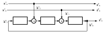 Figure 5. Trellis Systemic with Feedback Coder (3, 2, 3)
For systematic encoding, the input bits appear unchanged at the encoder output; this type of encoder cannot generate a catastrophic code. A catastrophic encoder is a coder for which at least one code word with the finite Hamming distance corresponds to an input with an infinite Hamming distance.
For the track circuit the important thing is that a 2 bits / sec / Hz transfer rate is achieved with a coding gain at the same 3.6 dB noise signal ratio versus a no-coded transmission.
For track circuits, the optimum transmission frequencies are in the audio frequency band due to the limitations imposed by the broadcast channel.
For 200 Hz signal bandwidth and Trellis encoding spectral efficiency 2½ bits / sec / Hz, 252 bits to the reception in the window time of the current system can be sent. This leads the train to be able to receive 4 telegrams in a timely manner with the information required for the system. If the allocated band is increased at 300 Hz, four information telegrams can be sent to the train, each of 64 bits, without reaching the maximum spectral efficiency limit for Trellis encoding. These four telegrams will be transmitted from two different points of the track to the moving train. Using a systematic parity convolution coder, a 45-bit telegram will be obtained; the remaining bits up to 64 bits can be used to send additional information to the train or even to redundantly transmit vital information within the same telegram. The speed and distance information can be transmitted twice in the same telegram.
Practically the new telegram that is sent to the train will contain the following information:
- target distance – bits 0-7 and 33-41, contains 2 * 8 informational bits to transmit the distance where on the train can travel
- target restriction – bits 8-10, contains 3 bits of information to convey the target restriction this tells to the train if there is a reduction in speed or a change in the type of traffic
- Left doors – bit 11, an informational bit to transmit to the train if it is allowed to open the doors on the left side
- Right door – bit 12, an informational bit to send to the train if it is allowed to open the doors on the right side
- Entry into the controlled area – bit 13, an informational bit that informs the train if it enters or exits the system-controlled area
- Pass over – bit 14, an informational bit informing the train that there is an area where the train can lose the telegram over a short distance
- Current speed and target speed – bits 15-21 and 41-47, 2 * 7 informational bits informing about the train speed and target speed.
After applying the Trellis 2/3 modulated encoding with 8PSK and parity checking, the following distribution of information inside the telegram will be obtained:
Target distance-bits 0-12 and 43-55, vital double information
Target Restriction – Bits 13-16
Left – Right Doors – Bits 17-19
Entry into Controlled Area and Over – Bits Crossing 20-22
Current speed and target speed – bits 23-32 and 33-43, vital information doubled
Track circuit label bit 56-64.
Performing the optimal Trellis encoding is done by mapping the symbols to ensure maximization of the free distance between them. This mapping is done by using special software programs to obtain the maximum efficiency of the encoder.
The information telegram set out above contains 37 bits required for the on-board system to meet the safety requirements for automatic train movement. These 37-bit information bits are inserted into a systematic convolution coder with feed-back and parity verification.
The encoder will have at the output 3 bits for every 2 bits at the input. For the transmission of the symbols it is necessary to use an 8-level modulation and for the beginning the use of the 8PSK modulation is to be considered.
The most probable errors made by the decoder’s optimal soft decision interfere between the {e_n} and the {d_n} transmitted and the decoded signals, if they are close in terms of Euclidean square spacing. The free quadratic free distance is called free distance and is given by the relation
d2free = min where . (6)
For this, the codes must be designed to have the maximum free Euclidian distance and not for Hamming distance. The redundancy required for coding comes from expanding the signal set without increasing the bandwidth [13]. The mapping should be based on the grouping of signals in symbols with a large distance between the signal subsets. To maximize the free distance the map of the symbol set is used as shown in the example represented in Figure 6.
| S0 |
| S7 |
| S0 |
| S7 |
| S1 |
| S2 |
| S3 |
| S4 |
| S5 |
| S6 |
| d20=0.586 |
| d21=2 |
| d22=4 |
|
000 000 |
|
001 100 |
|
010 010 |
|
011 110 |
|
100 001 |
|
101 101 |
|
110 011 |
|
111 111 |
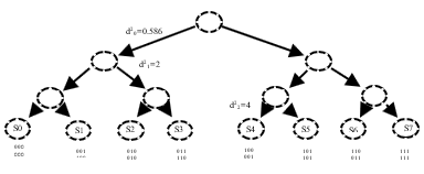 Figure 6. Symbol mapping by partitioning
3. Trellis track circuit – on-board receiver
The on-board receiver must receive the telegrams transmitted in the track from two distinct transmitters located in front of the train. The on-board receiver distinguishes these telegrams by differentiating the Trellis encoded modulated signals. The on-board receiver to process the received telegrams will have the block diagram shown in Figure 7.
| + |
|
Amplifier
|
| Filter |
| A |
| Delay Line |
| B |
|
Detect
|
| VC |
| DEM |
| Dec |
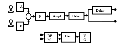 Figure 7. Trellis Track Circuit on-board receiver
The signal captured by the pick-up coils is summed by a differential summing circuit and then passed through the FTB bandwidth filter to keep only the useful signal. The detector block must separate the two telegrams received from the two separate transmitters. The telegrams arrive at a time difference dependent on the distance between the two transmitters and the gap between the telegrams introduced by the interlocking device. The first telegram is entered into a delay line until the second telegram arrives, then the telegrams are inserted into a demodulation and decoding block. The telegrams are inputted into a decision block that extracts the train data from the two telegrams, to transmit them to the train vital computer for execution.
The “Differential Summing Circuit” sums up the useful signals received by the pick-up coils, installed in front of the first axle of the train. The useful signal is passed through a band pass filter which only serves to extract the signals from the useful frequency bands.
The output from the “Band Pass Filter” is amplified and inputted into a delay line, until the second telegram is received. When the second telegram is received, the two telegrams are inserted into the “Demodulation and Decoding Block”.
The “Decoding and Demodulation Block” consists of two separate demodulators and decoders for the two telegrams. The signal decoding can be made “hard” by demodulation and then decoding, but this demodulation causes an irreversible loss of information received before decoding. At the receiver a sequence of sampled voltages corresponding to the transmitted bits are created. The received signal is sampled and forms a bit sequence, to decode this sequence which can apply a hard decision process that decodes the samples by assigning them pre-set voltage values. This process can make an erroneous decision especially in the comparison threshold area. In order to avoid these inconveniences of hard decoding, a soft demodulation-decoding is used, which means that the decoder operates directly on the non-quantified “soft” samples of the channel [14]. The patterns are expressed as vn = an + wn, where an is the discreet signal transmitted by the modulator and wn is the representation of the samples of the Gaussian noise addition process. The decoding rule of the decoded optimal sequence is to determine from the set “C” of the encoded signal sequences that can be produced by the coder-modulator system the sequence {an} with the Euclidian square minimal distance that fulfils the relation:
=Min with {an} C (7)
The Viterbi algorithm is used to perform this decoding-soft demodulation. This algorithm was proposed in 1967 and is an asymptomatic optimal decoding technique for convolution codes. It can be used to determine the sequence {an} of the encoded signal near the received non-quantized signal sequence {rn} provided that the sequences of the encoded signal generated {an} ∈ C. The coder determines the nearest encoded signal sequence, directly from the non-quantized channel output. The most probable errors made by the decoder’s soft decision-soft interfere between the {an} transmitted and {bn} decoded signals, if they are close one to another within the Euclidean quadratic distance, this distance is the free distance and is given by the relationship:
d2free=min where (8)
For this reason, system codes must be designed to have the maximum free Euclidean distance. For Trellis encoding, Viterbi decoder uses two metrics: branch metric and track metric. The branch metric is the measurement of the distance between what was transmitted and what was received and is defined for each path in the signal braiding. For “hard” decoding this branch metric is the Hamming distance between the expected bits and received bits. The track metric is the value associated with the trellis state, the value associated with each node, for the “hard” decision it corresponds to the Hamming distance of the most probable path from the initial state to the current state in the trellis. The most probable path is that with the smallest Hamming distance, measured on all possible paths between two states Hamming’s smallest distance minimizes the total number of errors and is the probable path with the smallest bit error ratio [15]. The Viterbi algorithm calculates metric paths for pairs of states using the branch and track metrics calculated for previous states [14]. The key points are as follows: the optimal path of the infinite past signal to all trellis states at time “n” is known. The algorithm extends these interactive paths from state “n” to state at time “n + 1” Choosing the best way, the algorithm applies a “good” tag for each new path or “cancelled” for all other paths that cannot be extended. The good paths tend to unite in the same historical path after a time “nd” with an effective delay decoding “D” (so the random change of the values of “d” is very likely to be less than “D”). The information associated with a transition is the historical “nD” path can be selected at the output. The received signals are considered to be disturbed by non-corrected Gaussian noise samples with variable σ2 in each signal size (in the subway system the noise is not Gaussian and patterns with system-specific disturbances must be used). The probability that at the given time the decoder makes an erroneous decision among the values of the associated signals for parallel transitions or to start making a series of mistaken decisions along the divergent paths for more than one transition from the correct path is called event probability error. At high noise signal ratios this probability is generally approximated by:
Pr(e) Nfree Q (9)
Where Q (x) is the Gaussian error integrity (10), and Nfree is the average of the numbers of neighbouring sequences with the dfree distance that go to any state in the transmitted signal sequence and come together after one or more transitions.
Q(x) = dy (10)
From the relationship (9) it can be approximated that at high noise signal ratios, the probability of event error associated with the target distance and then dfree becomes negligible.
For the embarked system the receiver uses the Viterbi algorithm and it implements two sets of patterns for comparison. The pattern sets for the disturbed signal must be correlated with the communication channel used and the disturbances that occur in it. Depending on the results obtained, the handset can automatically switch between sets of patterns to reduce the probability of error.
Because the 8PSK modulation is used on the receiver, a symbol rotation may occur due to interference or even oscillator instability. If in the Trellis diagram there is a large free square-space between symbols, then a small rotation of the diagram does not affect the received symbol, but if there is a small free square space between the symbols, then a small rotation of the diagram can change the decision boundaries of the symbols to make an erroneous decision. In most of the digital frequency carrier systems, the phase of the loop-specific carrier system has to be tracked. These loops estimate the phase shift of the received signal and decoder decisions, the estimated phase shift controls the phase of the demodulator carrier. For the new system, two symbols are used for each transmitted telegram to synchronise the demodulator with the modulator phase.
The output of the Trellis “Demodulation-Decoding block” is connected to the “Decision block” input. This block receives the two sets of decoded signals, each for a received telegram, compares them and checks the parity bits. Having two telegrams issued by two transmitters at different points of the runway, the train can extract the correct information even if the telegrams have been disturbed during the passage of the communication channel. The “Decision block” maps the bits from the Trellis decoder demodulator output to the telegram pattern and extracts the information about the received orders. The bits received for each telegram contain redundant information on speed and distance (maximum safety information for train running). The “Decision block” has four sets of information that regulate the train speed over a reserved and secured traffic distance. This information is received by the way of two telegrams sent through two transmitters separated from each other by the length of a track circuit.
The verified information is transmitted to the train computer for execution.
4. Trellis track circuit – transmitter
Taking into account the above mentioned functionality, the block diagram of the track circuit transmitter becomes that of Figure 8.
| TU |
| MU |
| Amplifier |
| Modulat 8PSK |
| Coding Trellis 2/3 |
| Data input |
| Oscillator |
| Interlocking |
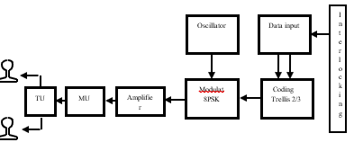 Figure 8. Trellis circuit block diagram scheme
The electronic interlocking system sends the orders to be executed and also the data which will be transmitted to the train, to the track circuit transmitter. The orders received contain instructions on how the track circuit transmitter should work, these modes being “detection mode” and “telegram mode”.
The information received from the interlocking is processed in the “Input block”. This block upon receipt of the “detection mode” order extracts from its own memory track circuit label and maps it to obtain the optimal Trellis encoding symbols. This mapping is required to optimize the encoding. The information is cyclically sent by two bits to the “Trellis Encoding block”. This operation is performed by the transmitter until another order is received.
“Telegram mode” is executed upon receipt of the order received from the interlocking. On receipt of this order the transmitter receives the information, which must be included in the telegram to be sent to the train, maps this information to obtain the optimal symbols and sends these symbols to the “Trellis Encoding block”.
The “Input block” will also prepare the synchronization symbols needed to synchronize the receivers; these symbols are included in the train telegram or in the detection message.
The “Trellis Encoding block”, can be that shown in Figure 5, it is a block that encodes the two information bits received from the “Input block”. The “Encoding block” performs Trellis’ systemic with feed-back coding and parity verification. The block encodes the received information and sends it by three bits to the “Modulation block”.
The “Modulation block” is designed to modulate a carrier frequency with the three-bit symbol received from the “Encoding block”. The internal diagram of this block is given in Figure 10 and performs the modulation using the symbol diagram shown in Figure 9
| cosωt |
|
sinωt
|
| 0.92 |
| 0.38 |
| 0.92 |
| 0.38 |
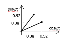 Figure 9. Symbols diagram 8PSK
|
Conv 3 bits |
|
Conv 2/4
|
|
Conv 2/4
|
| Osc 1/f2 |
| π/2 |
| ∑ |
| Filter |
| x |
| x |
| x |
| x |
| Trellis Symbols |
| Trellis 8PSK |
From the chart shown in Figure 9 it can be noticed that: for QPSK modulation where there are only two coordinates “I” and “Q”, for 8PSK it also need to define two amplitudes ± 0.38 and ± 0.92 to obtain the 8PSK modulation angles in the four quadrants.
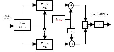 Figure 10. 8PSK Modulator block diagram
In the block diagram shown in Figure 10, the three-bit symbols from the output of the “Trellis Encoding block” are inserted into a serial / parallel converter, which separates the three bits on the three paths that define the symbol in the signal diagram. The bit 1 is used to control channel “I” , bit 2 to control channel “Q”, and bit 3 is used to define the two amplitudes. The amplitudes of the “I” and “Q” signals must be different in order to obtain the spatiality between the 8 phase states needed for 8PSK encoding states. The three bits command the 2-4 amplitude converters located on each channel “I” and “Q”, the bit 3 controls what amplitude is applied to each channel ± 0.38 or ± 0.92.
Outputs from the converters 2-4 are multiplied by the cosine and sine functions having the required carrier frequency, f1 or f2 for the line 1 and f3 or f4 for the line 2. These two signals are rotated continuously with 3π / 8 before forming the signal pulse to avoid that the signal envelope instantly passes near zero. For an optimal transmission, where must always be a difference between two consecutive symbols of 112.50
The two waveforms obtained after multiplication will be summed and applied to the input of a “Band Pass Filter” that only selects the signal useful for transmitting through the communication channel.
The signal rotated at this point is described by the relationship:
Rn=Sn = * = = +j (11)
Where the “Sn “signal is
Sn = Ac = Accos + j Acsin = I + j Q; n = 0 7 (12)
At the output of the 8PSK modulator block, it is a Trellis-encoded-modulated signal that, in order to be transmitted through the communication channel, in our case the rail tracks, requires amplification and adaptation to achieve the maximum power transfer to the load. These preparatory operations are performed by the “Amplifier block” and the “Mu” and “Tu” blocks that make the adaptation with the cable or railway tracks.
5. Trellis track circuit – track receiver
The track circuit receiver has the function to make the decision whether the track circuit is free or occupied. In order to do this, the receiver has a schematic block as shown in Figure 11.
| TU |
| MU |
| F |
| A |
| D Trellis 2/3 |
| DEC |
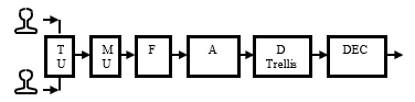 Figure 11. Trellis-8PSK track circuit block diagram
“Tu” and “Mu” units have the role of adapting impedances to get a maximum power transfer. The received signal is passed through a band pass filter that only keeps the useful frequency band
The amplifier “A” takes the signal from the output of the filter “F” and increases its power so it can be applied to the Trellis demodulator-decoder input “D”.
The demodulator – decoder Trellis “D Trellis” applies the Viterbi algorithm to the signal and extracts the received data. The data is extracted by “soft” decisions taken on signal samples that are compared to the noise-signal patterns. The patterns are made for the type of communication channel specific interference. For the track circuit, the receiver has two types of signal patterns, one with moderate disturbances and another for high disturbances. The receiver estimates the received symbols by applying these patterns and if the estimate does not match, then the receiver will change automatically the pattern sets to obtain optimal decoding and demodulation. The “demodulation-decoding block” also includes a tracking loop for the carrier phase. This block directly controls the frequency of the demodulator. Trellis demodulation and decoding at the track receiver is made identically to the on-board receiver. The symbols on the output of the Trellis demodulator-decoder block are introduced into a “Decision block”.
The “Decision block” is designed to rebuild and check the track circuit label. If the label is correct, the receiver will make the free or occupied track circuit decision. The track circuit receiver also collects other signals transmitted by the neighbouring transmitters, retrieves the track circuit labels and sends the information to the interlocking system. The interlocking system will receive the message with all the labels collected by the track circuit receiver and will have an overview of all the status of the track circuits in that area.
6. Connection of Trellis track circuit equipment
In the track circuit connection scheme, the transmitters and receivers are connected to the rail at the same point via an adapter transformer that has the role of adapting the impedances so as to obtain a maximum power transfer for the 8PSK modulated signal with the carrier frequencies f1 and f2. Frequencies f1 and f2 are chosen to achieve the best transmission performance through the railroad communication channel. This choice of carrier frequencies can be done using the communication channel models described in [16].
| T3 |
| T2 |
| T1 |
| R3 |
| R2 |
| R1 |
| CDC1 |
| CDC2 |
| CDC 3 |
| TX1 |
| TX2 |
| TX3 |
| R1 |
| R2 |
| R3 |
Figure 12. Connection of Trellis track circuit equipment
The carrier frequency is chosen accordingly to the electrical characteristics of the respective section of the line, these characteristics being dependent on humidity, ballast, line, etc.
The operation of the CDC2 track circuit in the two operating modes is as follows:
“Detection” mode – the Tx2 transmitter conveys a 64-bit telegram made by Trellis 2/3 coding of the 8-bit circuit-specific identification tag and a 30-bit “0” and “1” string modulated at a frequency of 20 Hz. The telegram is received by the R1, R2 and R3 receivers, making the decision that the track portions between them and the transmitter Tx2 are free, and the receiver R2 checks the correct operation of the transmitter chain Tx2.
When the CDC3 track circuit is occupied by the train having the direction of going to the CDC2, the interlocking device decides to switch the Tx3 transmitter as well as the Tx2 transmitter in the “telegram” mode.
“Telegram” mode – the Tx3 transmitter conveys a 64-bit telegram composed by Trellis 2/3 coding of the 8-bit transmitter label Tx3 and a 30-bit string containing the information required for the ATP system. This telegram is received by the on-board receiver as well as the R3 receiver that check the transmission chain as well as the receiver R2 which recognizes the transmitter identification tag Tx3, making the decision that the CDC2 is free.
“Telegram” mode – the Tx2 transmitter transmits a 64-bit telegram composed by Trellis 2/3 coding of the 8-bit transmitter label Tx2 and a 30-bit string containing the information required for the ATP system. This telegram is received by the on-board receiver which has doubled the information received, benefiting from the diversity principle, as well as the receivers R3 and R1 which decide that the CDC1 and CDC2 are free and the receiver R2 is checking the transmitter chain Tx2.
When the train pass on the CDC2 track circuit, the transmitter Tx2 and Tx1 are switched to “telegram” and the Tx3 transmitter is switched to “detection” mode. The command of the transmitter operations in both modes is performed by the interlocking system according to the train movement authority, and this system also provides the 30-bit string required for the ATP system
It is noted that for the operation of this track circuit there is no need for alternating the carrier frequencies to separate the signals of the neighbouring track circuits. This separation is done digitally by recognizing the labels transmitted. Alternating the carrier frequencies is only to help the receiver to easily separate the telegrams conveyed by two consecutive transmitters.
Identification tags may also be received at greater distances after two or more track circuits and their receivers extract the respective label and send it to the interlocking device, which sees an overview and takes the decision that the distance between the receiver and the transmitter whose label has been received as “free”.
Therewith the interlocking system can transmit to the train many telegrams using more than two transmitters, in this case the train has several telegrams that contain the same ATP information with multiple track circuit labels, which leads to a more efficient extraction of the ATP data system even in the case of Dirac disturbances. The limitation is given only by the window time available for telegram reception and the time required to extract the useful information, this being for an ideal line without loss and without attenuation.
In the case of real railway lines, there are losses due to ballast resistance and attenuations due to the constructive impedances of the railway. And in order to transmit the modulated signals on the carrier frequency “f” by the transmitters at a great distance, compensation capacitors can be installed, at each 50m or more. Compensation capacitors have the role of creating resonance points on the carrier frequency used, so it can pass on distances greater than the length of a track circuit. The length of the subway track circuit is about 250 meters, making it ideal for subway trains used.
7. Conclusions for the Trellis track circuit
The new track circuit with TCM aims to solve two of the problems encountered in the operation of the current track circuits, namely the loss of the telegram by the train and the false occupation of the track circuits in front of the train. These two problems emanate due to the Dirac impulses which arise in the return traction current path.
The new track circuit uses the transmission diversity principle to solve the loss of the telegram by the train.
Due to the limitation imposed by the length of the telegram, it was necessary to use Trellis 2/3 convolution code with a 8PSK signal modulation
The new telegram contains a tag for each transmitter, which it is used to identify free-circuits but also help the train to distinguish between received messages. By using these labels, the second problem encountered in the current track circuits, namely the false occupation of the track circuit in front of the train due to the Dirac disturbances occurring on the traction return side, is solved. The receiver will periodically receive telegrams transmitted from several transmitters and these telegrams are spaced from each other with the time required to travel on the distances from the transmitters to the receiver.
The realization of these circuits requires specialized FPGA circuits that can perform complex functions necessary for the coding-decoding and modulation-demodulation operations of the signals used. Due to these complicated systems the reliability is decreasing but this can be avoided by using good quality components.
Data loss caused by electromagnetic perturbation, especially due to the electrical arch in the return current path, is decreased drastically by using multiple transmitters. On the other hand, the data loss can increase due to 8PSK modulation but this is compensated by using multiple identical telegrams transmitted from different points and a good Trellis code.
The incident response time of the on-board equipment is improved by using the Trellis code and multiple similar telegrams.
The new track circuit uses a new rail connection concept, namely a magnetically coupled return coil with two coils that are tuned to deliver maximum power transfer from the transmitter to the track as well as from the track to the track circuit receiver.
Future works will be done with the scope of improving this new track circuit by finding a suitable Trellis code for metro line conditions and which fits the patterns used by the Viterbi algorithm
Conflict of Interest
The authors declare no conflict of interest.
- M. Enulescu, “Track circuit with space-time coding” International Conference on Applied and Theoretical Electricity (ICATE), 2016. DOI 10.1109/ICATE 2016.7754690
- Bombardier Transportation – Safety Analysis of OC Functions
- Bombardier Transportation – Track circuit TI-21M technical manual M2
- Data description for track circuit M2 – Bombardier Transportation
- On-board equipment description M2 – Bombardier Transportation
- http://webspace.ulbsibiu.ro/macarie.breazu/ACM/Codare Predictiva.pdf
- www.complextoreal.com Trellis Coded Modulation tutorial
- Trellis-Coded Modulation with redundant signal sets part 1 introduction Gottfried Ungerboeck 1987 IEEE communication magazine
- Telegram Decoder Software Block Specification – Tigris ATP/ATO Vehicle Equipment Platform Coded Track Circuit Interface, CTI. (GBSIG document) – Bombardier Transportation
- EBICAB 800 Telegram Display Utility, Software Description – Bombardier Transportation
- Functional description, Supervision of contact positions – Bombardier Transportation
- Functional description M2 – Bombardier Transportation
- Trellis-Coded Modulation with redundant signal sets part 2 State of the art Gottfried Ungerboeck 1987 IEEE communication magazine
- Viterbi Decoding of Convolutional Codes MIT 6.02 draft Lecture notes October 2010
- www.complextoreal.com Coding and decoding with convolutional codes tutorial 12
- M. Enulescu “Communication Architecture for Public Metropolitan Subway Transportation System” PhD. Thesis, “Politechnica” University Bucharest 2016