Applied Horizontal and Vertical Geothermal Heat Exchanger with Heat Pump System to Provide Air Conditioning for an Academic Facility in Mexico
Applied Horizontal and Vertical Geothermal Heat Exchanger with Heat Pump System to Provide Air Conditioning for an Academic Facility in Mexico
Volume 2, Issue 3, Page No 1064-1069, 2017
Author’s Name: Daniel Alcantar Martínez, Oskar Javier González Pedrazaa), Crisanto Mendoza Cavarrubias, J. Jesus Pacheco Ibarra, Jorge Alberto Rangel Arista
View Affiliations
Faculty of Mechanical Engineering, Universidad Michoacana de San Nicolás de Hidalgo, UMSNH, Morelia, Michoacán, México
a)Author to whom correspondence should be addressed. E-mail: oniblueoskar@gmail.com
Adv. Sci. Technol. Eng. Syst. J. 2(3), 1064-1069 (2017); ![]() DOI: 10.25046/aj0203135
DOI: 10.25046/aj0203135
Keywords: heat pumps, geothermal energy, geothermal heat exchanger

Export Citations
At present in Mexico, the renewable energy has become more important due to the great dependence of the country for fossil fuels. Within the several applications of renewable energy, there are the geothermal applications for the air conditioning of spaces. This technology employs heat pumps that interexchange heat with the ground. This technology is relatively young in Mexico, leaving a large field for study and application throughout the country. In this way, to calculate the correct sizing of geothermal heat exchangers, it is necessary to calculate the thermal loads of the complex in which this technology of geothermal heat pumps using vertical heat exchangers type U will be installed, to perform the calculation of thermal loads Autodesk Revit® software was used, with which was possible to make a virtual model in detail of the botanical center that is located in Morelia, Michoacán, Mexico and belongs to the Universidad Michoacana de San Nicolás de Hidalgo (UMNSH).
This study shows the results of the analysis of the installations and determination of the thermal loads of the complex due to this type of infrastructure. By obtaining the values of the thermal loads, the dimensioning of the heat exchanger was archived, which will have to be installed to cover the thermal requirement of this system and his installation, in addition to the selection of the heat pump. This complex of 2 levels, where, on the first floor there are cubicles and laboratories and on the second floor, several common areas.
The design was developed in detail in Autodesk Revit 2015. After obtaining the thermal loads, the GLHEPro software was used for dimensioning the Vertical heat exchangers with the number and depth of the exchangers was obtained. the GLD 2014 software was used for dimensioning the Horizontal heat exchangers with the number and depth of the exchangers was obtained.
Received: 28 April 2017, Accepted: 11 June 2017, Published Online: 15 July 2017
1. Introduction
Climate change is, according to experts, one of the greatest challenges facing humanity. This means that all public and private actors in global society must work together to reduce greenhouse gas emissions and adapt them territorially and sectoral to the potential effects so that we build a prosperous, sustainable and peaceful future [1].
Mexico presents in most of the territory medium and low enthalpy resources that are not exploited for the generation of electricity, and to which they are not used for direct uses. In Mexico, geothermal energy is solely employed to power generation. Direct use is still in a developing phase and currently it is restricted to supply bathing and swimming facilities. Geothermal heat pumps usage is minimal and underdeveloped without available data.[2] Geothermal energy is an alternative that can be used to produce electricity, store energy for heating and air conditioning devices in various facilities, and provide heat for a variety of commercial and industrial processes. Due to the constant temperature in the subsoil, a geothermal heat pump system typically has better performance than conventional systems. Geothermal heat pumps are used around the world to heating and cooling of buildings. Heat pump efficiency relies on the temperature of the fluid that provides the heat, in the side of ground, which is affected by the annual temperature profile and the pits distribution [3]. Low Temperature Geothermal Energy (LTGE) is the energy accumulated in the field generated from the heat exchange with the atmosphere at low temperature, it is an alternative energy source capable of satisfying the energy demand for domestic heating and cooling.An alternative to collaborate with the environment and the application of sources of renewable origin:
Horizontal Geothermal heat exchangers (HGHEs) with vertical springs have been increasingly used in Geothermal Sytem of Heat Pumps (GSHP). The current studies have been carried out by utilizing field trials and simulations focused in reveal the heat transfer mechanisms of HGHEs to procure an adequate performance of heat exchenge [4]. In [5] it is analized a solution of the interaction between a Photovoltaic generator (PV) and a GSHP to be used in a residential building. The main goal is to review the operative functioning of a self-sufficient system that enable the maximal self-consumption in the building itself: these systems can provoke a major penetration of Renewable energy sources in a complex energetic context.
Vertical geothermal heat exchangers are more common to be installed in areas where there is not enough space to place horizontal type heat exchangers. For the installation of the type of vertical exchanger configuration, drilling is performed in a very small space of land; The advantage of having a vertical type configuration is that it has a lower temperature fluctuation, which gives higher values of the operating coefficient.
Figure 1 shows schematically the operation of a heat pump with geothermal heat exchangers. In Mexico, the construction of an air conditioning system by means of heat pumps by means of geothermal heat exchangers has not been reported. Therefore, the present study studies the technical viability of the installation of this type of systems in national territory.
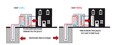 Figure 1. Operating of a conditioning system using a Heat pump with geothermal heat exchangers.
2. Case Study
Revit® software was used to calculate the thermal loads, which is contained within Autodesk® CAD software. This software allows to detail the whole and its spaces, for the calculation of the thermal loads of the complex. The case study refers to a building consisting of 2 levels, in the first level are the laboratories of sinecology, mycology, vascular and non-vascular plants, Palynology and sanitary. On the second level is a cafeteria, herbarium area, a silver reception area, quarantine area, multipurpose room and library. The calculation of thermal loads is essential for the selection of the different heat pumps to be installed in the system, as well as the dimensioning of the air ducts and the geothermal heat exchanger system. In Figure 2, show different views of the resort on its facade and plan views of the distribution of spaces.
The construction of the model on the Autodesk Revit® platform is specifically done using the Building Information Model (BIM) technique, and includes architectural design, structural engineering, MEP and construction. BIM is the process of generating and managing building data during its lifecycle, using dynamic real-time, three-dimensional building modeling software to reduce time and resources in design, construction and calculation. This process produces the building information model (also abbreviated BIM), which covers building geometry, spatial relationships, geographic information, as well as the quantities and properties of its components. The software has a basic of international climatic data, which allows, in the software, to locate the exact region of the building, as well as its orientation. When detailing each internal component of the model the software is able to determine the thermal loads through a year and with this determine the loads of summer and winter. The software is based on the methodology ASHRAE 2005[6].
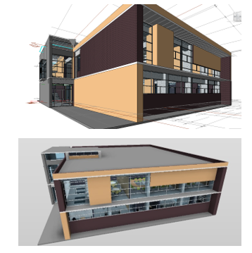 Figure 2. 3D view of the outer facade of the complex.
In this platform, it is possible to calculate the thermal loads for both summer and winter, to locate in detail the location of the complex to increase the accuracy of the calculation of thermal loads due to solar incidences in walls, ceilings and windows, as well as infiltrations due to the Air currents of the area in question, in addition to allowing the dimensioning of the air distribution ducts. Table 1 summarizes the overall calculation of the maximum and peak values shown and flux densities of the entire complex, can be noted that the maximum cooling load is 65.6 kW and maximum load Heating is 1.28 kW. With this we can appreciate that the requirement of these educational facilities will be primarily in cooling mode.
Table 1. Herbarium Summary
| Entries | |
| Types of construction | Educative Center |
| Area (m²) | 756.16 |
| Volumen (m³) | 2,080.20 |
| Calculation Results | |
| Maximum value of total cooling load (W) | 73,906 |
| Maximum cooling value (month and hour) | May 02:00 p. m. |
| Maximum value of sensitive cooling load (W) | 65,602 |
| Maximum latent cooling load value (W) | 8,304 |
| Maximum cooling capacity (W) | 73,906 |
| Maximum value of cooling airflow (L / s) | 5,821.20 |
| Maximum heating load value (W) | 1,286 |
| Maximum value of heating air flow (L / s) | 5,572.30 |
| Checking Sums | |
| Density of cooling load (W / m²) | 97.74 |
| Density of the cooling flow (L / (s · m²)) | 7.7 |
| Cooling flow / load (L / (s · kW)) | 78.77 |
| Cooling area / load (m² / kW) | 10.23 |
| Density of heating load (W / m²) | 1.7 |
| Density of heating flow (L / (s · m²)) | 7.37 |
3. Analysis and Results to the Virtual Model of the Facility
It was conducted a loads analysis to cooling and heating, in order to select the proper zones in the complex to install the Air conditioning System. Once review, the value of load in the two working modes comes from the herbarium, followed by the library and then all the laboratories at the bottom and finally the multipurpose room and the editing room, this can be seen in Figure 3. Figure 4 shows the thermal loads of heating and appreciated that spaces having larger load are the library, the multipurpose room and assembly, and Zone of reception of plants, this is because they are zones with great incidence solar by the windows and of conduction by ceiling and walls, which will be the zones of priority for the system of conditioning.
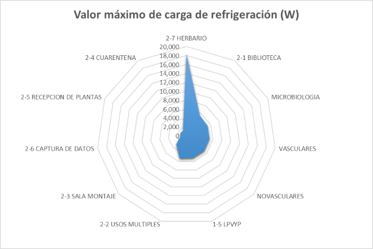 Figure 3. Distribution of thermal loads of the school of refrigeration loads (W)
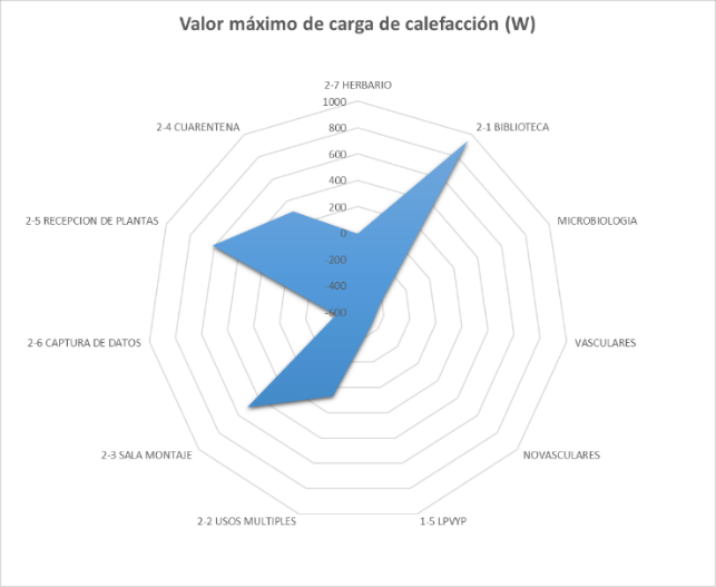 Figure 4. Distribution of heating loads of the school of heating loads (W)
In Figure 5, the monthly average thermal loads shown in cold mode, these loads are due to the transfer of heat generated by the occupants, electrical equipment and laboratory equipment, they are also considered heat gains due to windows and the incidences of the sun, and the transfer of heat through the walls of the enclosure, ceilings and floors. As you can notice the months in which it will require more use of the cold mode of the heat pump will be from the month of May until October of each year.
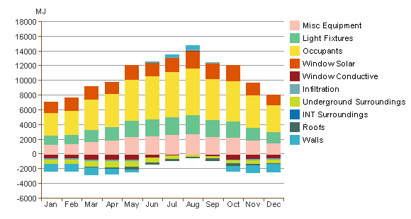 Figure 5. Average monthly heat load in cold mode
In Figure 6, the monthly average thermal loads shown in heat mode, these loads are due to the transfer of heat emitted by the occupants, electrical equipment and laboratory equipment, they are also considered heat gains due to windows and the incidences of the sun, and the transfer of heat through the walls of the enclosure, ceilings and floors. It can be noted in the figure that the months in which the system will be used in heat mode will be the months from November to March of the year.
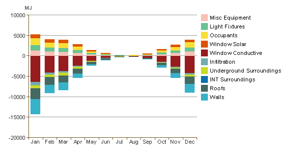 Figure 6. Monthly average heat load in heat mode
In Figure 7, the consumption of electricity over a year shows, you can note that the maximum consumption occurs in the months of December to March, in these months do not have daylight saving and lighting Solar is for few hours so the electricity consumption is higher while the other months have a lower consumption due to the little use of lighting.
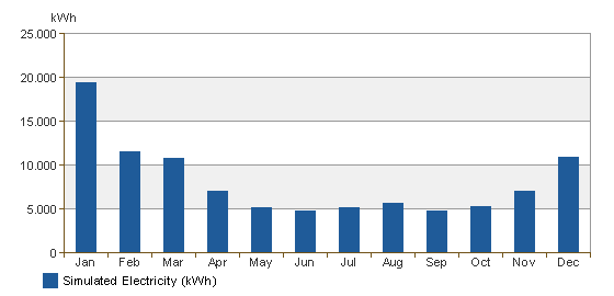 Figure 7. Monthly consumption of electrical energy of the complex
4. Results and Discussion
After obtaining the value of the thermal load under which the whole complex will be operating, the dimensioning of the heat exchangers was started, for which two commercial software’s were used. In the first instance, we will perform the dimensioning of the vertical heat exchangers and then the horizontal ones, it is worth mentioning that, between the two systems, the thermal load of the complex will be divided.
In order to calculate the length of the heat exchanger, we will use specialized software tools. In this case, the GLHEPro® numerical tool was used, which specifies the type of heat exchanger to be installed, physical characteristics of the vertical heat exchanger, Specifications of the floor type, in addition to the type of coolant to be used in the heat exchangers which in this case would be water. After all the values required for the simulation of the well are loaded, the thermal loads are introduced to the system which were calculated by the Revit® software.
The U-type heat exchanger, proposed for the storage and recovery of geothermal energy from the well and subject of the present analysis, converting the soil into a thermal sink, the pipes were considered to be high density polyethylene (PAD), the grout is of a mixture of concrete, silica sand and water, the material around the terrain, are those found in the field in which these exchangers are being installed, the type of soil in the area will provide the values of the thermal properties. The average thermal conductivity of the soil obtained by the rheological drilling column is 0.8657 W / (m ° K) and the thermal resistance of the exchanger is 0.3048 ° K / (W / m), the volumetric flow of the system is recommended by IGSHPA [7] of 1.9962 L / s, the thermal conductivity of water 0593 W / (m ° K) and heat capacity of 4173.36 kJ / (° Km 3). In Figure 8 the scheme proposed heat exchanger is shown.
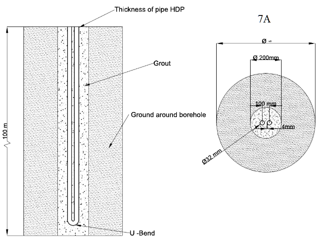 Figure 8. Schematic of the geothermal heat exchanger.
Once the calculation was carried out in the software, the results obtained are from the need of 4 vertical exchangers with a depth of 88.29 m and a total drilling depth of 353.16 m, and a distance between interchangers of 4.57 m. The maximum temperature value will be 25.51 ° C and with a minimum of 6.23 ° C and with temperature peaks ranging from 31.53 ° C and -6.67 ° C. With these temperatures. It can be concluded that it may be necessary to add some antifreeze to the system for its operation and with that the system works properly. The software has a tool to perform the optimize of the appropriate size, using this tool the software tells us that the length of the exchangers will be 81.15 m with a total drilling length of 324.6 m, and a separation distance between exchangers of 4,572 m. The maximum temperature will be 25.93 ° C and with a 6.5 ° C and the temperature peaks at 32.22 ° C and -6.67 ° C. With these temperatures, the need to add some antifreeze to the system is also confirmed for its operation.
Figure 9 shows the proposal for the interconnection of the heat exchangers, the figure shows the dimensioning of pipe exchangers, like the inkjet heads and refrigerant recovering also the dimensioning of the accessories for installation, As well as the mass flow in gal/min in each of the sections of the heat exchanger. For sizing, the horizontal heat exchanger shown in Figure 11 was performed using the software GLD 2014, this tool allows for vertical and horizontal dimensioning exchangers with a large number of configurations. This software uses an iterative method for its solution by feeding parameters divided into specifications of fluid, soil, piping, configuration and auxiliary equipment.
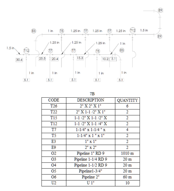 Figure 9. Schematic of the air conditioning system using a geothermal heat pump
Figure 10 shows the behavior of the maximum average temperature of the exchangers during operation over 10 years of operation. It can be observed on the temperature profile curve the effect provoked to the underground due the operation of heat exchangers on this soil. From the graph, it is clear that variations are minimal as well as soil perturbances. The variance of 1°C demonstrate that along 10 years of usage the system will not affect the surroundings or the environment where installed.
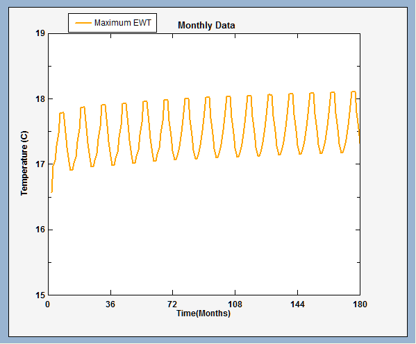 Figure 10. Behavior of the set of heat exchangers with maximum temperature
For the dimensioning of the horizontal heat exchanger shown in Figure 11 was performed with the help of GLD 2014 software, this tool allows the design of vertical and horizontal exchangers with a large number of configurations. This software uses an iterative method for its solution by feeding proper parameters: such as specifications of fluid, soil, piping, configuration and auxiliary equipment.
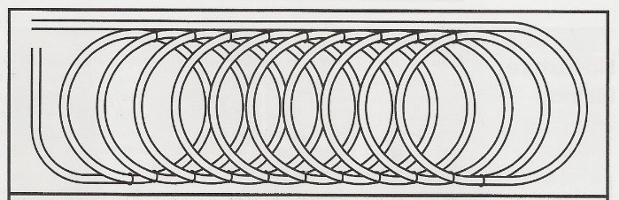 Figure 11. Slinky horizontal geothermal heat exchanger for trenches
The parameters of the pipe comprise the thermal conductivity of the pipe, and its dimensions as outer and inner diameters and the die, plus the type of internal flow of the pipe. In the configuration of the heat exchangers the software has the different types of trenches that can be applied, in this study we used the trench slinky type, this is a pipe coil, this technique requires less space than other techniques, using only 4 lines with a separation of 6.1 m between them to a depth of 1.8 m and a width of 20 cm, the particular measures of the slinky type heat exchanger is a diameter of 91 cm and a separation between them of 52 cm. The next thing is to quantify the heat gains of the system by use of pumps and auxiliary equipment, in this case only a 2.5 HP heat pump is taken into account to be able to move all the fluid through the heat exchangers to the heat pumps.
After entering the parameters required by the software as in the previous calculation, the iteration is performed to be able to quantify the dimensions of the system, in this case the result obtained is 4 trenches with a total length of 101 m, whereby each Trench will have a length of 25.3 m, the total length of the system will be 1347.6 m of pipe
In Table 2, the selection of the heat pump for space with increased demand and usage shown. The criterion of the selection of heat pumps is made by means of the air flow of the system for each space and these must also meet the requirements of thermal load in both cold and heat mode [7]. These values are also obtained by the 3D model space subject of analysis which are shown in Table 2. In Mexico it has a large number of companies that provide conventional air conditioning systems, in this case it was decided to make the selection of heat pumps in the catalog of the company Daikin.
Table 2. Selection of heat pump for Herbarium
| Space | Maximum cooling load value (W) | Maximum cooling load value (BTU/hr) | Cooling airflow (L/s) | Maximum heating load value (W) | Maximum cooling load value (BTU/hr) | Heating air flow (L/s) |
Daikin Unit |
| HERBARIUM | 18,308 | 62,469 | 1,480 | 17,295 | 59,013 | 1,359.60 | 48 |
| LIBRARY | 5,463 | 18,641 | 441.8 | 947 | 3,231 | 531.1 | 30 |
| LBM | 8,047 | 27,458 | 654.7 | 897 | 3,061 | 623.3 | 42 |
| MULTIPLE USES | 5,287 | 18,040 | 427.6 | 70 | 239 | 401.8 | 42 |
| ASSEMBLY ROOM | 2,920 | 9,963 | 236.2 | 512 | 1,747 | 285.1 |
5. Conclusion
The purpose of this work was to design the system for air conditioning using heat pumps with U-type vertical heat exchangers through the use of different software for a student laboratory complex located in Morelia, Michoacán, Mexico. With this dimension, it makes clear the feasibility of installing these systems in Mexican territory and the learning of technical and field capacities in a multidisciplinary way. In addition to the development of a methodology for the integration of different software such as Autodesk Revit® and GLHEPro®, in which it was possible to model the building in detail for the calculation of thermal loads and the dimensioning of vertical heat exchangers. The length of the exchangers will be 81.15 m with a total of 4 heat exchangers, and a separation distance between exchangers of 4,572 m In addition to the horizontal heat exchanger system which are formed of 4 trenches with a total length of 101 m, Whereby each trench will have a length of 25.3 m, the total length of the system will be 1347.6 m of pipe, the heat pumps selected for the highest priority spaces for its Daikin models 30, 42 and 48. Which meet the need for mass air flow and thermal load in both heat and cold.
Conflict of Interest
The authors declare no conflict of interest.
Acknowledgment
The authors wish to acknowledge the SENER and CONACYT institutions for their support in CeMIE_Geo projects, particularly the P-30 project.
- S. General, “GEOTHERMAL Outlook Limited for Some Uses but Promising for Geothermal Heat Pumps,” 1994.
- N. Lenhardt and A. E. Götz, “Geothermal reservoir potential of volcaniclastic settings: The Valley of Mexico, Central Mexico,” Renew. Energy, vol. 77, pp. 423–429, May 2015.
- A. Capozza, A. Zarrella, and M. De Carli, “Long-term analysis of two GSHP systems using validated numerical models and proposals to optimize the operating parameters,” Energy Build., vol. 93, pp. 50–64, Apr. 2015.
- D. Wang, L. Lu, and P. Cui, “A new analytical solution for horizontal geothermal heat exchangers with vertical spiral coils,” Int. J. Heat Mass Transf., vol. 100, pp. 111–120, Sep. 2016.
- A. Franco and F. Fantozzi, “Experimental analysis of a self consumption strategy for residential building: The integration of PV system and geothermal heat pump,” Renew. Energy, vol. 86, pp. 1075–1085, Feb. 2016.
- 2005 ASHRAE, ASHRAE. 2005. Capítulo 30: Nonresidential Cooling and Heating Load Calculations (Cálculos de cargas de calefacción y refrigeración en zonas no residenciales), 2005 ASHRAE Handbook – Fundamentals Roth, Stephen. 2006. 2005.
- C. Remund, R. Carda, P. Rawlings, and J. Bose, “GROUND SOURCE HEAT PUMP RESIDENTIAL AND LIGHT CEMMERCIAL DESIGN AND INSTALLATION GUIDE.” Oklahoma state University, Stillwater, Oklahoma, 2011.