Multiclass Myoelectric Identification of Five Fingers Motion using Artificial Neural Network and Support Vector Machine
Multiclass Myoelectric Identification of Five Fingers Motion using Artificial Neural Network and Support Vector Machine
Volume 2, Issue 3, Page No 1026-1033, 2017
Author’s Name: Jawad Ahmad1, a), Ammar Mohsin Butt2, Muhammad Tanveer Riaz1, Shoaib Bhutta1, Muhammad Zeeshan Khan1, Inam-Ul-Haq3
View Affiliations
1State Key Laboratory of Power Transmission and System Security, School of Electrical Engineering, Chongqing University, Chongqing 400044, China.
2Department of Electrical Engineering, International Islamic University, Islamabad 44000, Pakistan
3Department of Electrical Engineering, National University of Science and Technology (NUST), Islamabad 44000, Pakistan
a)Author to whom correspondence should be addressed. E-mail: Jawad.ahmad@cqu.edu.cn
Adv. Sci. Technol. Eng. Syst. J. 2(3), 1026-1033 (2017); ![]() DOI: 10.25046/aj0203130
DOI: 10.25046/aj0203130
Keywords: Electromyography, Discrete Wavelet Transform, Artificial Neural Network, Support Vector Machine

Export Citations
The research in Neuro-Prosthetics is gaining more significance and popularity as the advancement in prosthetics control allows amputees to perform even more tasks. Indeed, the improvement of classification accuracy is a challenge in prosthetics control. In this research, a system is developed in order to improve the multiclass classification rate. Two classifiers namely Artificial Neural Network(ANN) and Support Vector Machine(SVM) are trained to recognize five different myoelectric motions of hand fingers. The Electromyography(EMG) signals are acquired using surface electrodes placed on the forearm at specific nodes. The signal conditioning is performed using two stage filtering and amplification followed by digitization process. The final version of EMG signals is correlated in joint time and frequency domain for best feature vectors done via Discrete Wavelet Transform (DWT). The feature vectors are used to train the ANN and SVM. The classification results show an exceptional performance of ANN with classification accuracy of 98.7%. over the SVM, which is 96.7%.
Received: 30 May 2017, Accepted: 28 June 2017, Published Online: 15 July 2017
- Introduction
A lot of work is done in the field of bionics and kinematics. The purpose is to identify the finger movements. Electromyography is a procedure commonly used to assess the muscular activity created by skeletal muscles when fired by neurons. These signals can be used to detect muscular diseases and disorders etc. Some of the applications are found in prosthetics control where EMG signals are used for the robotic control of hands, arms and fingers. The most frequently used approaches for acquiring EMG signals are surface and intramuscular methods. In first case, surface electrodes are placed on specific nodes on forearm in pair form. A reference or a neutral point is defined usually taken as bone and a single electrode is placed on it. The EMG signal picked up from nodes have a small amplitude usually in millivolts and contains noise of line and skin impedance. Signal conditioning of these EMGs is needed to further processing. Feature extraction is a significant step following signal acquisition. It helps to identify and extract useful information present in signals. These feature vectors are used for training, validation and testing of the classifier used for classification. Thus, the pattern recognition method has an important role.
A technique used for multi-channel classification of surface EMG using support vector machine (SVM) and signal based wavelet is reported in [1]. The algorithm is trained to classify EMG signals of six hand movement. The technique showed an overall classification accuracy of 95%.
There are some works which describe the use of SVM either in medical findings [2] or related to myoelectric prosthetics control. Crawford et al. [3] described the use of SVM for Myoelectric classification. The purpose is to control a robotic arm with 4 degrees of freedom. A set of seven single electrodes placed on the forearm were employed to distinguish eight hand gestures. The results showed a classification rate was over 90%,
The hand gesture EMG recognition based on ANN technique has been reported in [4,5]. A back-propagation ANN classifier with Levenberg-Marquardt training algorithm was used. The network used features in time and frequency domain. The results showed that ANN can classify six different hand movements (left, right, up and down) with an error rate of 11.6 %.
Similarly, Bitzer and Smagt have also used SVMs to identify six different finger actions with ten double differential electrodes placed near to the wrist [6]. The accuracy was between 90-94% for relax and pronation postures of arm. Another work reported by Lucas et al. [7], shows a multi-channel classification problem where Myoelectric identification was performed in order to distinguish six different movements of the hand based on SVM and wavelet coefficients. Final results show that the optimal wavelet selection favors the performance of classifier, giving an average error rate of 5%.
Some work related to the five fingers motion identification has been reported in [8]. The two-layered feed forward neural network was trained to identify 16 features from five fingers motion. The ANN was able to classify the features with the maximum classification rate of 96.7%.
The main aim of this research is to improve the classification rate by designing a hardware and software based system. A hardware module consists of filters and amplifiers is designed for capturing an optimum EMG signal in meaningful frequency range. Firstly, the EMGs are acquired using electrodes placed on nodes and are conditioned by filters and amplifiers. The conditioned signals are digitized and read in MATLAB which are then subjected to transformation in joint time and frequency domain by Discrete Wavelet Transform (DWT). The features returned by DWT are availed to trained the ANN used to classify five finger movements. A total of 500 utilized feature vectors will be fed up to the input of neural network for training, validation and testing. To compare the performance results, SVM is also trained. Furthermore, the classification performance of ANN and SVM is compared when classifiers are subjected to testing data. Finally, the efficiency and robustness of SVM and ANN is also discussed.
The classification results of ANN show an improved classification rate of 98.7% achieved in five fingers classification. The performance results of ANN showed an edge over the performance of SVM which is 96.7%. The network robustness is depicted by the superb performance plots of the neural network.
2. Material and Method
This research is carried out in flow stated in Figure 1 below. The block diagram shows the phases for EMGs processing.
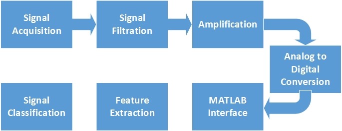 Figure 1: Flowchart of the research
2.1. Electrode Placement
Signals are acquired from five fingers using surface EMG Electrodes. Gelled Ag/AgCl electrodes are used as it helps in creating good contact between skin and electrode thus mitigating skin impedance. To avoid crosstalk and distortion suitable size and distance of electrodes is chosen. The size of electrode is chosen 10mm as suggested by SENIAM [9] and European inventory. For each finger two electrodes are used in pair configuration. These electrodes are placed between motor units and tendon insertion of muscles with the inter-electrode distance of 20mm between them. For each finger, the electrodes are placed on forearm on specific nodes as shown in Figure 2. The reference electrode is placed at back side of hand on bone giving a reference signal to differential amplifier used for filtration in next step.
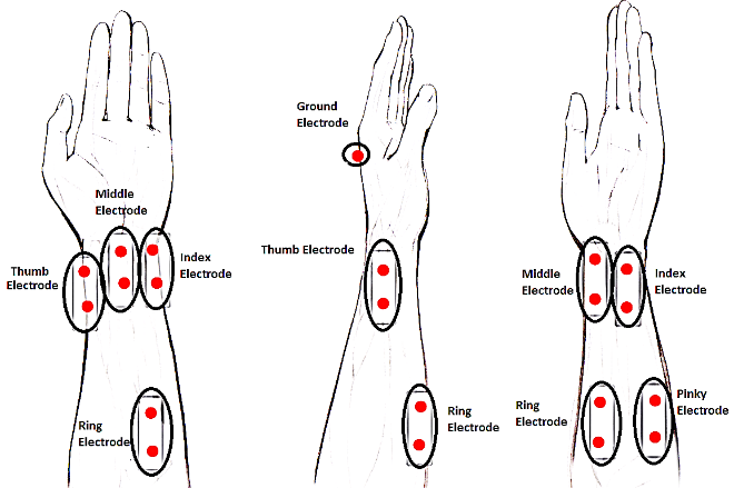 Figure 2: Electrode placement on forearm for signal acquisition
A stereo cable is used to connect electrode and the signal conditioning circuit. One end of the cable has a dual-channel stereo jack and other end consists of alligator clips.
2.2. Signal Conditioning Circuit
In order to remove noise from EMGs, a signal conditioning circuit is implemented as shown in Figure 3. It consists of five channels for five fingers respectively. Stereo jack sockets are utilized to connect the connecting wires.
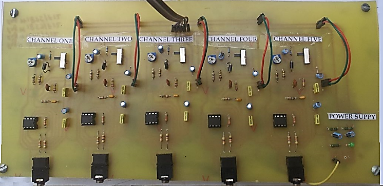 Figure 3: Hardware module used for signal conditioning
2.3. Differential Filtration
Signals acquired from electrodes contain noise due to skin Impedance and connecting leads. An instrumentation amplifier AD623 is used to remove noise. The signals are read with respect to reference electrode and their difference is amplified as shown in (1). The common mode rejection capability of the amplifier removes noise from signals. The read signals are free of noises such as power lines noise. Indeed, the CMMR is an important factor for any differential amplifier as it eliminates any correlated signals that come from power sources or electromagnetic devices. The CMMR determines how well the input signals have subtracted. AD623 provides better CMRR, high input impedance and strong DC voltage suppression, therefore, keeping the error to a minimum. The CMRR for amplifier remains constant up to 200 Hz. Figure 4 shows the schematic of the instrumentation amplifier
used for differential filtration.
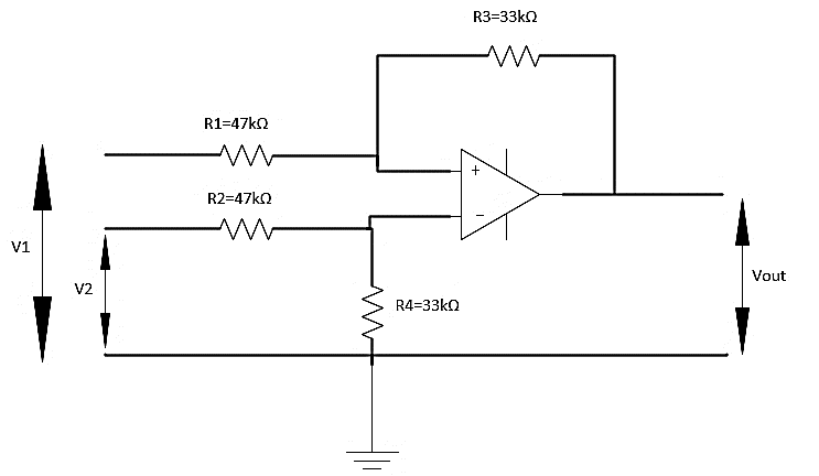 Figure 4: Circuit diagram for differential amplifier
Where R1=R2=47 kΩ and R3=R4=33 kΩ
2.4. Bandpass Filtration and Amplification
To select the useful range of frequencies and amplification, a low voltage operational amplifier LMV358 having voltage range between 2.7 V and 5.5 V is used. LMV358 is dual low voltage amplifier. First op-amp is used as frequency selective bandpass filtering and amplification. The frequency range is selected between 100-500 Hz. Figure 5 shows the schematics of the bandpass filter and amplifier.
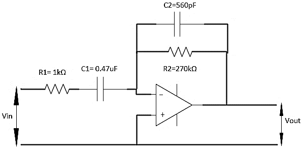 Figure 5: Circuit diagram for bandpass filter
In figure given above R1 = 1 k, C1 = 0.47uf, R2 = 270 k, C2 = 560pf. The equations for bandpass filter are given as follows:
To enhance the resolution of recoded signals, amplification is also required. Amplifier of high quality having adjustable gains is used. The second operational amplifier in LMV358 is used as inverting amplifier with adjustable gain. The values of resistors are selected such that the op-amp provides negative gain of 250, therefore, during each acquisition of EMG signal the signal to noise ratio gets maximized and EMG signals are amplified to appropriate levels. Figure 6 shows the schematic of an inverting amplifier used for amplification.
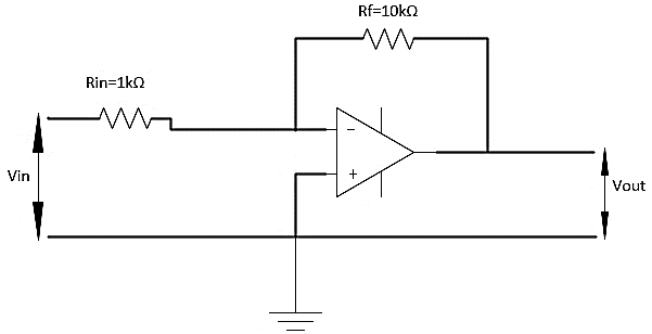 Figure 6: Circuit diagram for an inverting amplifier
After amplification, EMG signals are subjected to a peak detector circuit. It consists of diode which renders only positive deflections of the signal. The random nature in amplitude of EMG signals exists even after rectification. To extract amplitude related information, the concept of smoothing is adopted by using the RC combination as a low pass filter to suppress high frequency fluctuations in the EMG signal. The deflections in EMG signal appear smooth and the peak value of EMG signal is easily captured by RC combination.
After passing the EMG signals through various steps of signal conditioning, filtration, amplification and rectification, the final signal is obtained as shown in Figure 7. This is the positive signal with average amplitude lies in range of 0-5V as ensured through previous amplification.
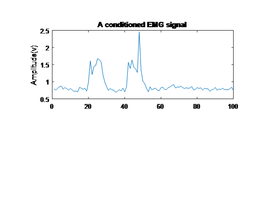 Figure 7: The final waveform of a conditioned EMG signal
2.5. Analogue to Digital Conversion
Signal conditioning steps remove noise and amplify the signals to appropriate levels. These signals then need to be used in Matlab for further processing. An Arduino Uno board based on ATmega328P is used for analog to digital conversion. It uses a built-in 10-bit ADC at a sampling rate of 8.6 kHz according to the Nyquist criteria. The analog voltages are mapped between 0 and 3 V with resolution of 1024.
Digital signals from the Arduino are read in Matlab through serial interface of Arduino. 9600 baud rate is used. For ease of coding a hardware support package of Arduino is used in Matlab.
2.6. Feature Extraction
Feature extraction is important step for any classification problem as it helps to extract important information from the signals. The features acquired in this step are used as training data to classifier. Wavelet transform transforms the stochastic EMG signals into time and frequency based information which is helpful in finding the harmonic contents and better diagnostic possibilities as compared to the conventional Fourier transform. The rapid variations within a signal can be accurately studied and analyzed using wavelet transform. As can be seen in the Figure 9, the Fourier transform forms a constant frequency resolution as the signal is divided into constant time window. However, in the case of wavelet transform the signals are divided into different time windows with different range of frequencies which provides better allocation for high frequency components in the signal. Another advantage of wavelet transform is simple computation and less complexity as compared to the Fourier transform.
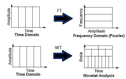 Figure 9: Comparison between Fourier and wavelet transform
Since, the DWT exhibits good frequency resolution at low frequencies and good time resolution at high frequencies [10], therefore, the DWT is chosen as a feature extraction technique for surface EMG signal. The DWT coefficients of a signal x(n) may be obtained as:
Where a is scale, b is translation and ѱ(n) is a discrete wavelet. The Daubechies 4 or db4 wavelet window is used as it provides best correlation with the EMGs, therefore, giving best feature vectors for training the classifiers. The DWT is achieved by passing the signal x[n] through two complementary filters, a low pass filter having impulse response g[n] and a high pass filter having impulse response h[n] as shown below:
The application of two filters gives the approximation and detailed coefficients containing information about the shape and sharp variations of the signal respectively. For capturing sharp variations in the five fingers EMG signals, the detailed coefficients are used as features for training the classifiers.
Hence, the DWT helps to analyze the EMG signals at different frequency band with different resolution which is helpful to extract best feature vectors for training ANN and SVM.
2.7. Feature Classification
The features extracted from EMGs are utilized to train ANN and SVM.
2.8. Support Vector Machine (SVM)
Support Vector Machine (SVM) was first introduced by Vapnik and Chervonenkis at 1965. SVM is a supervised learning technique used in the field of machine learning. In SVM, the training is reformulated in such a way to achieve a quadratic programming problem whose solution is unique and global. The detailed information regarding the SVM can be found in [11]. SVM is a binary classifier whose output is estimated by the given empirical data:
The problems related to non-linear problems are solved by mapping the original data into a feature space. The mapping data is linearly separable in feature space. Function , which maps the training vector into a higher dimensional space, requires to belong to a dot product space. The dot product of mapping function is termed as kernel:
The group of data that is mapped in high dimensional linear space is divided in two labeled classes by a hyperplane. The labeled classes are shown as:
To ensure maximum margin between separating classes, the selection of a suitable hyperplane is necessary. To construct this hyperplane, we need to solve the following quadratic problem:
where is called the slack variable, which takes values for each . It is related to the concept of soft margin, whereas, C is the tuning parameter used to tolerate errors and balance the training data. Equation (11) can be solved by the introduction of a Lagrange multipliers through next expression as:
Solving (12) leads to an optimal decision function as:
The decision function shown in (14) depicts that the classifier has an extension in terms of a subset of the training data. Those patterns whose is non-zero, are termed as support vectors. The non-linear classification can be achieved by introducing different kernel functions, which computes the inner product of vectors and . These typical kernels functions include lineal, quadratic and radial functions. The SVM inherently is a binary classifier and performs classifications on two class problems. To solve multiclass problems, like in our case for five fingers motion classification, we need to extend the capabilities of SVM to multiclass approach. Therefore, for multiclass SVM, (8) can be represented as:
The theme is to train 5 independent binary classifiers so that each one is trained to discriminate the training samples in only one class against all the remaining classes. For classifying a new sample, 5 classifiers work separately, the one giving largest output is chosen as an estimated class. This scheme is referred to as the one-against-all. It is simple, fast and accurate method to implement. The kernel function used for separating patterns is a quadratic function having box constraint level equal to 1.
2.9. Artificial Neural Network
In this paper, the pattern recognition of the features is done using the ANN as shown in Figure 10.
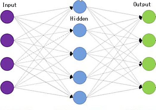 Figure 10: The structure of Neural Network
The first output neuron in the hidden layer is given by (16).
Whereas is the output vector from the input layer, IW is the weight matrix of input, is the hidden layer transfer function and is the hidden layer bias function. Similarly, the first output neuron of the output layer can be expressed as:
Whereas is the output vector of output layer, LW is the weight matrix of output, is the output layer transfer function and is the bias vector of output layer. The network is a two-layered feed forward network having with a sigmoid transfer function in hidden layer and a SoftMax transfer function in the output layer as depicted in (18) and (19) respectively.
The network has 10 neurons in the hidden layer. The network is trained using scaled conjugate gradient backpropagation. The backpropagation is performed on the whole feedforward network in order to improve the results of ANN. This technique is referred to as fine tuning of a whole ANN. The theme is to retrain the whole network in a supervised fashion. In backpropagation training, the goal of training is to mitigate which is the square error taken over all n vectors.
Where and is the desired output and network output for node k and p respectively During training, the backpropagation algorithm fine-tunes the weights that are randomized initially respective to the steepest gradient along the surface of error. Weights are set as per their influence to the output which is done by the method of reusing the squared error signal through weights layers. Training is proceeded by the presentation of each normalized input vector z and its equivalent output target vector d, until each becomes smaller than the maximum allowable error . The presentation of complete set of training data to the network is called an epoch.
The performance of ANN is evaluated based on cross entropy. During the learning process, the ANN goes through various stages in which the reduction rate of error is very slow which can influence the learning process. For solution, the mean square error (MSE) is replaced by cross entropy error function. The results of error function show a better performance having a shorter stagnation period. The original MSE function for all training patterns is given by
where represents the target value and is the actual value of network. In the backpropagation technique, the error through the iterative updates of weights is minimized for all training patterns. In practice, this approach allows the network to have a good performance but convergence rate is slow. Therefore, in order to accelerate the backpropagation, we propose the following cross entropy error function to be minimized:
To minimize the error , each weight is updated proportional to the partial derivative of , with respect to weight. Using the mean square error, the partial derivative of with respect to is
By using the cross-entropy error function, (20) becomes:
Hence, the error signal that propagates back from each output unit becomes proportional to the difference between target value and actual value. This leads to a better network performance along with shorter stagnation period. A total of 350 samples are used to trained the ANN. The network performance is tested using 150 samples of EMG data.
3. Experiments
3.1. Simulation of Signal Conditioning Circuit
Schematics and simulations of the circuit are carried out using Proteus Software. The differential filter removes the noise by amplifying difference of two signals. This removes the noise due to the skin impedance and terminals of the connecting wires. The bandpass filter selects the frequency range of 100-500 Hz and provides 250x gain, thereby, removing the power line noise and giving an optimum signal in meaningful frequency range. The millivolt signal is amplified to more than 2 volts which is appropriate level for further processing. The impedance of wires interfacing the electrodes and the circuit board is matched to, that of the board mainly, the input of differential amplifier for ensuring the maximum power transfer.
The circuit’s performance shows that this configuration of hardware components is suitable for EMG signal acquisition. The fingers movement is depicted in Figure 11. The EMG signal is recorded as a result of individual finger movement. A total of 500 samples are taken from finger patterns which is then used for feature extraction followed by the training, validation and testing of the classifier (ANN).
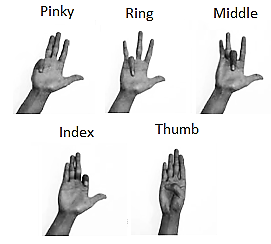 Figure 11: The five fingers movement pattern for EMG signal acquisition
The EMG data acquired from five fingers are sent via serial interface to the Matlab workspace. Shown in Figure 12 are signals for five fingers read through serial port of Arduino in Matlab. The Arduino Hardware support package is used in Matlab for having simplicity in serial interface. This package allows to import the libraries of Arduino in Matlab, therefore, giving a sophisticated way to program the controller in Matlab and to read serial data from its serial interface. The data read in Matlab is stored in an array form in the workspace of Matlab.
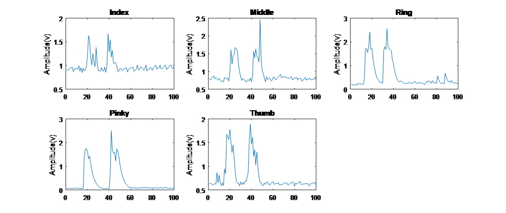 Figure 12: The five fingers EMG signals read in Matlab
3.2. Feature Extraction and Classification
The feature extraction and classification was performed in Matlab 2017a software. Discrete Wavelet Transform (DWT) was used for feature extraction from EMG signals. The Daubechies 4 or db4 wavelet window is used for best correlation with EMGs as discussed previously. It provides approximation and detailed coefficients containing information related to shape of signal and sharp variations in the signal respectively. The detailed coefficients or high frequency components as shown in Figure 13 are used as feature vectors for training of the classifier.
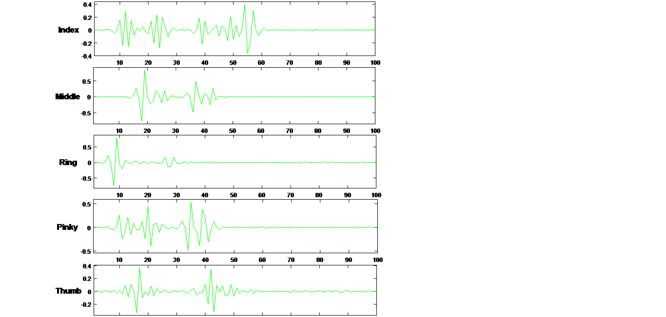 Figure 13: The DWT detailed coefficients of five fingers respectively.
3.3. Cross Entropy
During training the ANN, there is a measure of error between computed outputs and the desired target outputs of the training data. The most common measure of error is called mean squared error. The performance of ANN based on cross entropy is shown in Figure 14(A). The results show best performance of 0.024758 at epoch 27. The steep fall of training curve shows best performance of ANN achieved during training. The performance of ANN is tested by 150 samples of data which is depicted in the curve of testing. The ANN converges to output in a very small stagnation time as can be seen in Figure 14(A).
3.4. The Confusion Matrix
|
|
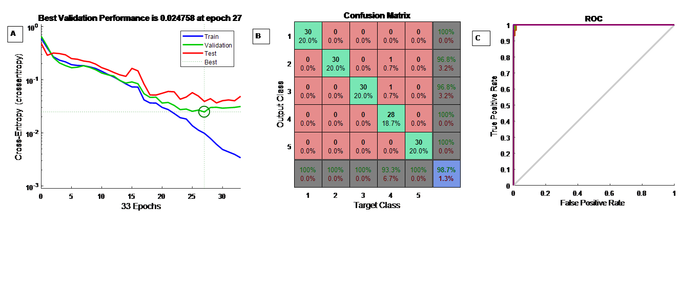
The confusion matrix is used to estimate the quality of the output of a classifier on the specified data set, providing an insight of the errors and specially the types of errors made during the classification. The diagonal elements characterize the number of samples correctly classified by the classifier, while non-diagonal elements are those that are misclassified by the classifier. The higher values in diagonal depicts the better accuracy of the classifier. The theme is to divide the correct predictions by total no of predictions made by the classifier to output the percentage accuracy as given below.
Whereas corresponds to correct classification taken over ? patterns. The confusion matrix showing the results of ANN classification using 10 hidden neurons are shown in Figure 14(B). The confusion matrix of SVM is shown in Figure 15.
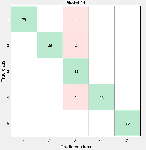 Figure 15: The confusion matrix of SVM
The overall accuracy of classification is calculated to be 96.7%. The ANN matrix shows an excellent classification accuracy of 98.7% which is an edge over the accuracy of SVM. The classification accuracies using SVM for each finger are given in Table 1 whereas the classification results of ANN are listed in Table 2.
3.5. The Receiver Operating Characteristics
Receiver Operating Characteristic (ROC) curve is also used to assess the classifier output performance. ROC curve plots the True Positive Rate (TPR) on Y axis, and False Positive Rate (FPR) on X axis. This characterizes an ideal point, a false positive rate, to lie on the top left corner of the plot, giving a FPR of zero, and a TPR of one. This type of characteristic gives a greater area under the curve (AUC) for achieving best performance. The Figure 14(C) shows the ROC of ANN output. Figure 16 shows the ROC of SVM. The ROC curve of ANN is the representation of an excellent performance, giving AUC = 0.983, whereas, the ROC for SVM is 0.978. The steepness observed in curves of both ANN and SVM is also very significant, thereby, maximizing the TPR
while minimizing the FPR.
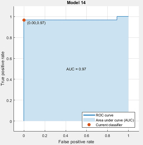 Figure 16: The ROC of SVM
Table 1 Classification accuracy of five fingers using SVM
| Finger Name | Total Samples | Classified samples | Accuracy | Error |
| Index | 30 | 29 | 96.67% | 3.33% |
| Middle | 30 | 28 | 93.3% | 6.7% |
| Ring | 30 | 30 | 100% | 0% |
| Pinky | 30 | 28 | 93.3% | 6.7% |
| Thumb | 30 | 30 | 100% | 0% |
| Overall Accuracy & Error | 96.7% | 3.3% | ||
Table 2 Classification accuracy of five fingers using ANN
| Finger Name | Total Samples | Classified samples | Accuracy | Error |
| Index | 30 | 30 | 100% | 0% |
| Middle | 30 | 30 | 100% | 0% |
| Ring | 30 | 30 | 100% | 0% |
| Pinky | 30 | 28 | 93.3% | 6.7% |
| Thumb | 30 | 30 | 100% | 0% |
| Overall Accuracy & Error | 98.7% | 1.3% | ||
4. Conclusion
A noise free and an optimum EMG signal is captured by the signal conditioning circuit. The feature vectors obtained through DWT is best for feeding the classifier as it provides maximum correlation with EMGs. The binary SVM is made capable of solving five class finger recognition problem via multiclass approach. The SVM showed an overall accuracy of 96.7% with an average error rate of 3.3%. The two-layered feed forward network showed an excellent performance over the SVM in the classification of EMG signals showing a minimum error of 1.3%. The accuracy is improved to 98.7% with 10 neurons being used in hidden layer. The network is converged in a small stagnation time. In future work, the two-layered feed forward network can be extended to multilayered deep networks, for improving the classification accuracy. Moreover, the multiclass SVM and ANN network proposed can be used to recognize several hand gestures at certain degrees of freedom proving more robustness in the prosthetics control specially for amputees.
Conflict of Interest
No any.
Acknowledgment
We thank Ammar Mohsin Butt, Inam-Ul-Haq, Muhammad Tanveer Riaz, Shoaib Butta and Muhammad Zeeshan for their assistance.
- M. -Franc¸oise Lucas, A. Gaufriau, S. Pascual, C. Doncarli, D. Farina,” Multi channel surface EMG classification using support vector machines and signal-based wavelet optimization,” Biomedical Signal Processing and Control, vol.3(2), pp. 169–174, November 2007.
- G. Kaur, A. S. Arora, and V. K. Jain, “Multi-class support vector machine classifier in EMG diagnosis,” WSEAS Trans. Sig. Proc., vol. 5, pp. 379-389, 2009.
- B. Crawford, K. Miller, P. Shenoy, and R. Rao, “Real-time classification of electromyographic signals for robotic control,” Proc. 20th Nat. Conf. Artificial Intell. (AAAI 05), 2006, pp. 523-528.
- M.R. Ahsan, M.I. Ibrahimy, O.O. Khalifa, “Hand Motion Detection from EMG Signals by Using ANN based Classifier for Human,” Computer Interaction, Modeling, Simulation and Applied Optimization (ICMSAO), 2011 4th International Conference on , pp.1-6, April 2011.
- M.R. Ahsan, M.I. Ibrahimy, O.O. Khalifa, “Electromygraphy (EMG) Signal based Hand Gesture Recognition using Artificial Neural Network (ANN),”Mechatronics (ICOM), 2011 4th International Conference On , pp.1-6, May 2011.
- S. Bitzer and P. van der Smagt, “Learning EMG control of a robotic hand: towards active prostheses,” Proc. IEEE Int. Conf. Robotics and Automation (ICRA 06), 2006, pp. 2819-2823.
- M.-F. Lucas, A. Gaufriau, S. Pascual, C. Doncarli, and D. Farina, “Multi-channel surface EMG classification using support vector machines and signal-based wavelet optimization,” Biomed. Signal Process. Control, vol. 3, pp. 169-174, 2008.
- M. Ariyanto et al., “Finger movement pattern recognition method using artificial neural network based on electromyography (EMG) sensor,” 2015 International Conference on Automation, Cognitive Science, Optics, Micro Electro-Mechanical System, and Information Technology (ICACOMIT), Bandung, 2015, pp. 12-17. doi: 10.1109/ICACOMIT.2015.7440146
- Freriks, B., Hermens, H., Merletti, R., Stegeman, D., Blok, J., & Rau, G. European Recommendations for Surface Electromyography Results of SENIAM Project. Roessingh Research and Development, (2000) pp. 13-54.
- Eldin Henry Shroffe D, P. Manimegalai, “Hand Gesture Recognition Based on EMG Signals Using ANN,” International Journal of Computer Application Issue 3, Vol. 2, April 2013.
- V. N. Vapnik, Statistical Learning Theory, Danvers, MA: Wiley Interscience,1998.