EEG Mind Controlled Smart Prosthetic Arm – A Comprehensive Study
EEG Mind Controlled Smart Prosthetic Arm – A Comprehensive Study
Volume 2, Issue 3, Page No 891-899, 2017
Author’s Name: Taha Beyrouthya), Samer Al Kork, Joe Akl Korbane, Mohamed Abouelela
View Affiliations
American University of the Middle East, Egaila, Kuwait
a)Author to whom correspondence should be addressed. E-mail: taha.beyrouthy@aum.edu.kw
Adv. Sci. Technol. Eng. Syst. J. 2(3), 891-899 (2017); ![]() DOI: 10.25046/aj0203111
DOI: 10.25046/aj0203111
Keywords: EEG, Prosthetic arm, Sensors, Mind-controlled, Robotics, Emotive, Signal processing

Export Citations
Recently, the field of prosthetics has seen many accomplishments especially with the integration of technological advancements. In this paper, different arm types (robotic, surgical, bionic, prosthetic and static) are analyzed in terms of resistance, usage, flexibility, cost and potential. Most of these techniques have some problems; they are extremely expensive, hard to install and maintain and may require surgery. Therefore, our work introduces the initial design of an EEG mind controlled smart prosthetic arm. The arm is controlled by the brain commands, obtained from an electroencephalography (EEG) headset, and equipped with a network of smart sensors and actuators that give the patient intelligent feedback about the surrounding environment and the object in contact. This network provides the arm with normal hand functionality, smart reflexes and smooth movements. Various types of sensors are used including temperature, pressure, ultrasonic proximity sensors, accelerometers, potentiometers, strain gauges and gyroscopes. The arm is completely 3D printed built from various lightweight and high strength materials that can handle high impacts and fragile elements as well. Our project requires the use of nine servomotors installed at different places in the arm. Therefore, the static and dynamic modes of servomotors are analyzed. The total cost of the project is estimated to be relatively cheap compared to other previously built arms. Many scenarios are analyzed corresponding to the actions that the prosthetic arm can perform, and an algorithm is created to match these scenarios. Experimental results show that the proposed EEG Mind-controlled Arm is a promising alternative for current solutions that require invasive and expensive surgical procedures.
Received: 05 April 2017, Accepted: 11 June 2017, Published Online: 26 June 2017
1. Introduction
In recent studies, the World Health Organization (WHO) reported that about 15% of the world’s population suffers from a form of disability, half of which cannot afford health care [1]. Due to various political, economic, scientific, and demographical reasons, the overall rates of amputees and limb dysfunction patients are increasing [2]. There are over 10 million amputees worldwide, out of which 30% are arm amputees [3]. Although prosthetic limbs exist since decades, they are not very natural in terms of operation and interaction with the environment. They require undergoing an invasive surgical procedure [4]. The main goal of such complex procedures is to reassign nerves and allow amputees to control their prosthetic devices by merely thinking about the action they want to perform as stated by the John Hopkins Applied Physics Laboratory.
A team at the John Hopkins University developed a robotic arm in their physics lab that is controlled by brain signals [5]. The arm has 26 joints, and can lift up to 45 pounds. It is based on an idea, which can be altered to fit any need, from someone missing just a hand to an entire limb. Engineers from Ossur, one of the biggest bionic arms markets in the world, designed an artificial bionic advanced leg and it was tested on a farmer who lost a leg [6]. A comparison was made between the bionic and the mechanical artificial legs, in which the engineers noticed some flaws in the mechanical leg, and thus causing the user to fall while walking if wrong amount of pressure was applied to the toe where the leg is connected. The bionic leg, on the other hand, was constructed out of more than one piece. The knee, the foot and the leg were assembled to create a fully functional bionic limb [7]. This limb has a brain of its own, and can sense what surrounds it by the processors that analyze the inputs. According to the head of this group of engineers, the leg costs more than a few sedan cars.
Prosthetic limbs need to be measured and fitted to the patient for his needs [8]. To apply prosthetics on a patient, intense medical observation and a training course for the patient are needed so that he can use the limb comfortably. There are several techniques used as a means of controlling robotics arms, and the top three methods are highlighted hereafter. The first method is to use an electroencephalogram (EEG) device [9], which will record the person’s brain waves when he is thinking of a certain action or implementing a facial expression. These readings are then converted to commands for the arm. The author in [10] states that the mind regulates its activities by electric waves registered in the brain that emits electrochemical impulses having different frequencies, which can be registered by an electroencephalogram. For instance, beta waves are emitted when a person feels nervous or afraid with frequencies ranging from 13 to 60 Hertz. Alpha waves are emitted when a person feels relaxed mentally and physically with frequencies from 7 to 13 Hertz. On the other hand, delta waves are emitted when a person is in a state of unconsciousness. The advancement in technology made it possible to process these EEG frequencies and data directly in real time by the use of a brain-computer interface which is a combination of hardware and software.
The second method is the surgical implantation. The arm is surgically connected to the person’s torso. Connections are also made to the nerves to allow the reading of electrical signals so that these signals can then be filtered and converted to commands. The last control method consists in using sensors, which will be connected to the robotic arm in order to take specific readings. Some of the most common sensors used in this case are EMG, gyroscope, and accelerometer sensors. This will allow the user to be aware of the position his arm can be in as well as expand and enclose it. All the arm types used are summarized and compared with each other in Table 1 hereafter in terms of usage, flexibility, cost potential.
Table 1. Arm Types comparison
| Arm Type | Usage | Flexibility | Potential |
| Robotic | Using mounts | Depends on the motors, material and design | Big potential with the rise of 3D printers |
| Surgical | Surgically Implanted | Depends on the training and the physiotherapy | Very high especially for the war victims |
| Bionic | Very effective for everyday usage |
Depends on how well can the processor analyze the surroundings
|
Good potential, especially with the microprocessor revolution |
| Prosthetic | Similar to the surgical limbs, but less medical attention | Very high flexibility (custom made for each person using exact measurements) | Overshadowed by the surgical and the robotic limbs |
| Static |
No mechanical use
|
Not flexible | No potential |
The control techniques used are summarized and compared with each other in Table 2 hereafter in terms of cost, installation, degree of control and accuracy.
Table 2. Control techniques comparison
| Type | Approximate Cost (U.S. Dollars) | Installation | Degree of Control | Accuracy |
| EEG | 100 – 400 | Detachable | Complete control | Accurate |
| Surgical | 10,000 – 120,000 | Permanent | Complete control | Very accurate |
| Sensors | Below 100 | Detachable | Limited | Accurate |
The EEG method is not only cost effective, but it is also accurate and gives the patient complete control of the arm. It also gives the user the luxury of taking it off when feeling discomfort. EEG is a noninvasive method of monitoring brain activity. Typically, it uses electrodes placed on the outside of the head, and measures voltage oscillations in the neurons of the brain caused by ionic current. It has been used in medical applications for a very long time. The Emotiv EPOC is an example of an EEG headset with 14 sensors and having an internal sampling rate of 2048 Hz. After filtering the signals, it sends the data to the computer at approximately 128 Hz. The signals are transferred from the headset to the computer through wireless technology. This offers much greater mobility, and instead of requiring a special gel, the electrodes of the EPOC simply need to be dampened using a saline solution that in disinfectant and common.
The project presented in this paper aims to develop a low-cost and versatile human-like prosthetic arm controllable via brain activity using EEG neuro-feedback technology. The arm is equipped with a network of smart sensors and actuators that give the patient intelligent feedback about the surrounding environment and the object in contact. It also allows the arm to react and execute pre-programmed series of actions in critical cases (extremely hot or fragile objects, etc.) A first prototype has been developed to test the prosthetic arm with the embedded electro-mechanical system. This prototype is controlled using flex sensors integrated within a wearable glove. A microcontroller is added to the system, thus allowing to perform programmed actions and tasks. The arm is created using a 3-D printer in order for it to be cost efficient. All parts are printed separately then assembled together. This prototype focuses on the arm-environment interaction. A second prototype based on the EEG control has also been developed and still under test. Preliminary experimental results show that the EEG technique is a promising and good alternative to other existing techniques.
2. System Architecture
The proposed system is divided into 4 major units [11] as shown in Figure 1:
- The Input Unit – EEG sensors
- The Processing Unit – Pattern recognition
- The Electro-Mechanical Unit – The arm
The Interface Unit – Smart sensor network
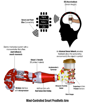
Figure 1. Mind-controlled smart prosthetic arm architecture
2.1. Input Unit
In this unit, brain signals were captured by an array of advanced EEG sensors communicating with a Signal Processing Unit via low-power and secure connectivity using Bluetooth technology. This device has an internal sampling rate of 2048Hz and 14 sensors arranged according to the international 10-20 System as shown in Figure 2 in order to cover the most relevant area over the brain. This allows a maximum and efficient coverage of the brain activity. EEG signals are acquired using the Emotiv EPOC wireless recording headset bearing 14 channels (AF3, F7, F3, FC5, T7, P7, O1, O2, P8, T8, FC6, F4, F8), referenced to the common mode sense [12].
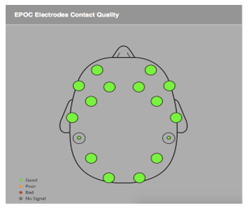
Figure 2. EEG 14-sensor arrangement
2.2. Processing Unit
The EEG signals provided by the input unit were sampled and processed on a lightweight wearable device – the Processing Unit. The processing activity consists of two main parts: a pattern recognition part that identifies different brain behavior captured by the input unit, and a command part that generates a series of commands to be sent to the mechatronics system of the arm.
This unit was programmed to distinguish between several states of the mind representing different levels of “meditation” and “focus”. Every mind state was captured and encoded to represent a set of desired tasks to be performed by the arm. Due to the diversity and the complexity of brain wave activities among different humans, machine-learning techniques were required to train patients to specific arm movements according to a set of mind states.
2.3. Electro-mechanical Unit
This unit was designed and built from various lightweight high-strength materials that can handle high impacts and fragile elements as well. It integrated servos capable of handling 800 oz.-in. of stall torque. These servos were strategically placed to minimize hardware and facilitate complex moves. A microcontroller was also integrated to this setup to provide the interface between the Mechanical Unit and the Processing Unit. It can also be programmed to perform a series of predefined movements, allowing the arm to have a sophisticated and realistic real hand behavior.
2.4. Interface Unit – Smart Sensor Network
This unit is composed of a network of smart sensors, including temperature, skin pressure and ultrasonic proximity sensors, accelerometers, potentiometers, strain gauges and gyroscopes. The main features of this unit allow the arm to interact with and adapt to the surrounding environment. Moreover, a bi-directional communication was required to give commands to the arm and provides feedback to the patient. This integrated network of sensors and actuators required custom communication protocols and networking techniques that allow seamless interaction and control between the arm and patient. By default, controlling the arm was handled by the brain (patient); however, it can be transferred to the arm to proactively protect itself against damage.
Due to its unique features, the proposed Mind-controlled Smart Prosthetic Arm should be able to improve the quality of life for millions of patients and their families around the world. Its low cost design makes it accessible for a wide range of beneficiaries, especially those with limited or no access to advanced health care.
3. Technical Specifications
3.1. Hardware Overview
| WiFi Communication |
|
EEG Headset
|
| Signal Processing Unit |
| Control Unit |
| Sensor Network |
|
Mechatronic System (The arm) |
|
Feedback About Surroundings
|
| On board the arm |
The Smart Prosthetic Arm architecture was based on an advanced electro-mechanical system controlled by EEG neuro-feedback technology. This architecture is divided into 4 main units in terms of hardware (see Figure 3 and Figure 4) [13]:
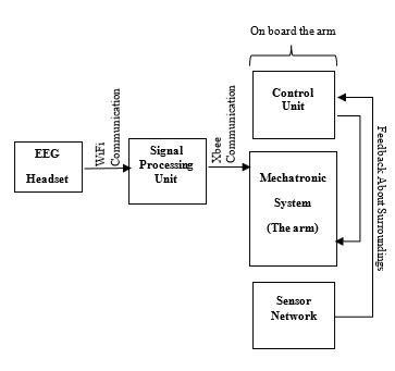
Figure 3. System overview – block diagram
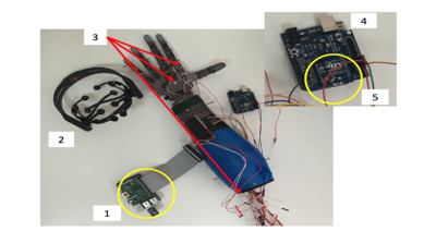
Figure 4. System overview – photo of the actual components
As shown in Figure 4, component number 1 is the processing unit that receives the EEG waves from the headset and communicates with the control unit; component number 2 is the Emotiv EEG headset with 14 sensors; component number 3 corresponds to the embedded sensors (temperature, proximity and touch); component number 4 is the control unit, which is Arduino based; component number 5 is the XBee driver (wireless communication with the processing unit).
The Data Sampling Unit includes 14 EEG sensors implemented in the EEG-based headset. This unit converts EEG signals to digital signals and send them to the processing unit through Bluetooth communication channel.
The Wireless Communication Unit includes low power connection Bluetooth module interfaced with the Raspberry III microcomputer. This part implements a communication protocol between the user (EEG sensors installed on the head) and the embedded microcontroller in the prosthetic arm.
The Computing and Processing Unit: Sampled EEG signals are channeled through the wireless communication unit to reach the Computing and Processing Unit, which is embedded in the arm and includes a Raspberry Pi III microcomputer, interfaced with an Arduino Mega microcontroller that handle the mechanical servo units installed in the arm. The main function of the processing unit is to treat the digitized EEG signals. It is programmed to compare between the headset reading and a set of premeasured patterns related to different states of the mind. Different mind states are captured and encoded to represent a set of desired tasks to be performed by the arm. This Unit is also programmed with multiple hand reflexes, triggered by the smart sensor network embedded in the arm. It gives the arm a human-like behavior via smooth movements and smart reflexes.
Finally, the Electro-Mechanical Unit includes nine servo motors installed on the 3D designed model. The 3D hand model is built from various lightweight high-strength materials that can handle high impacts and fragile elements as well. This unit integrates all servos, which are capable of handling 800 oz.-in. of stall torque. It is embedded in the arm and links servos to joints to perform different motions. The servos are strategically placed to minimize hardware and facilitate complex moves. A microcontroller is also integrated to this setup to provide the interface between the Mechanical Unit and the Processing Unit.
One of the main features of this arm is its affordability, which is accomplished mainly due to the fact that the arm is entirely 3D printed, which is one of the most affordable, yet durable ways of manufacturing such a product in this day.
For the process of building, different materials were used to create a full arm. The usage of different materials provided a more practical build.
The hand was created using a material called EcoPLA, which is PLA mixed with certain chemicals to provide a sense for heat recognition. This material can change color when exposed to heat. The added sensors provide visual aid to the user of the arm so that the user can estimate the heat of the held item. EcoPLA is considered to be a clean material, mainly extruded from starch, corn, and sugar cane, which makes it more environmental friendly. For the mechanical moving parts that need better endurance and will be exposed to more pressure, PLA is also used as the material for the build because of its strength, flexibility, and heat resistance, which makes it more reliable; therefore, it is the best material to execute the job with no flaws. It is also easily sanded and machined.
For the forearm, shoulder, and elbow, PLA is used to complete the build. PLA is a printing material that is easily machined under normal conditions, on the other hand ABS needs special heating bed during the printing. PLA is also an environment friendly plastic which can be created using a mixture of different plant substances, such as potatoes and corn, yet, it does not bio-degrade easily. PLA is also considered strong and rigid material, yet it has a lower melting temperature which makes it unreliable under pressure.
The project required the use of nine servomotors in different places in the arm. To make sure the hand is able to carry a load varying from 3-5 kg, first we had to know how much torque each servo motor needed. To get that, the following formula shown in (1) for the static mode is used:![]()
is the momentum; is the length between the force and the first angle ; is the length between the force and the second angle as shown in Figure 5.
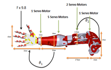
Figure 5. Prosthetic Arm Technical Specifications
For the dynamic mode of the servo motors, friction of the arm parts along with some other parameters were neglected. The following formula shown in (2) is used:![]()
is the force applied on the hand; is the length of the arm; is the polar movement of inertia; is the angular acceleration or polar acceleration.
The equation for the dynamic mode shown in (2) changes from one part to another (shoulder, wrist, hand or elbow).
The next calculations are obtained while the hand is in the static mode, not the dynamic mode. While the angles are equal to zero, the servos will be outputting their highest torque in the static mode as shown in Table 3.
Table 3. Load calculation for a servo motor
|
Mass (Kg) |
Force (N) | Wrist S. Torque | Hand S. Torque | Biceps S. Torque | Shoulder S. Torque | |
| 1 Kg | 9.8 | 1.96 | 3.43 | 6.615 | 7.889 | |
| 2 Kg | 19.6 | 3.92 | 6.86 | 13.23 | 15.778 | |
| 3 Kg | 29.4 | 5.88 | 10.29 | 19.845 | 23.667 | |
| 5 Kg | 49 | 9.8 | 17.15 | 33.075 | 39.445 | |
| 7 Kg | 68.6 | 13.72 | 24.01 | 46.305 | 55.223 | |
| 10 Kg | 98 | 19.6 | 34.3 | 66.15 | 78.89 | |
3.2. Dynamic Modeling of Prosthetic Arm
In the time domain, the mechanical model of the Prosthetic Arm can be represented as a generalized second order differential equation form for the translation motions as shown in (3):![]()
where: f(t) represents the applied tension forces in the two sides of the tendons to create displacement between fingers at different configurations, m is the mass of the movable part, x(t) is the displacement between fingers at different time, C1 is the friction damping coefficient for the translation motion , K1 is the spring constant . the same model can be restated for the torque at the elbow and shoulder joints as shown in (4):![]()
where: J is the mass polar moment of inertia (kg.m2) of the rotated part, q(t) is the angular displacement (rad.), C2 is the friction damping coefficient for the rotational motion , K2 is the rotational spring constant .
From the multibody dynamic model of the different parts of the Prosthetic Arm, we can get the required toque for each of the 8 motors at all possible movement configurations, the selection design value for the motors specifications was based on the maximum calculated required torque & Power.
3.3. Power Consumption
The power study of the proposed Smart Prosthetic Arm is divided into 2 major parts.
The EEG headset uses a lithium (Li) battery that provides up to 12 hours of continuous use when fully charged. If fully discharged (after 12 hours of usage), it can take up to 4 hours to be recharged. However, the charging process takes between 30 minutes to 2 hours when not fully discharged. Therefore, it is recommended to recharge it before 12 hours of continuous use. For safety reasons, the headset does not work while charging it.
The electro-mechanical system is composed of eight servo motors of rated power 0.5 Watts and 3.5 Watts, which are placed on different parts of the prosthetic arm (wrist, elbow, shoulder and fingers). Three servomotors with a rated power of 3.5 Watts are placed on the wrist, elbow and shoulder area to provide three degrees of freedom. In addition, five servomotors with a rated power 0.5 Watts each are used to control the five fingers. Thus, all the servomotors consume a total power of 13 Watts. A 5V battery with an output current of 2.6 Ampere is required to provide power to all servomotors embedded in the arm. The wireless communication unit operates when a 50 mA is supplied at 3.3 V, which requires a power of 0.165 Watts to operate.
In addition, a network of smart sensors is used, including temperature, skin pressure and ultrasonic proximity sensors, accelerometers, potentiometers, strain gauges and gyroscopes. These sensors consume a total current of 100 mA. The power consumption of the low-power single board computer (Computing and Processing Unit) is 0.1 Watts corresponding to a current of 30 mA. To power all the units listed above, the system requires a power source with an output current not less than 2.8 A and 5V as output voltage.
Two 10,000 mAh lithium ion batteries are chosen with an output current of 2A each. They include a charging circuit (via USB Cable), and a boost converter that provides 5V DC. These batteries have an 80% efficiency loss on both ends, meaning that it is not recommended to operate the arm while the battery is being charged. With these two batteries, the arm will be operational for 7 continuous hours knowing that the average hand movements per person during a day are equivalent to 1 to 3 hours of continuous movements depending on the daily activity performed. In conclusion, the whole system can be operational for 2 full days.
3.4. Smart Sensors
The sensors included in the proposed solution can be classified in two categories: user-end sensors and environment-end sensors. The first category consists of the 14 EEG sensors presented previously which are installed on the user headset.
As for sensors of the second category, their main feature is to allow the arm to interact and adapt to the surrounding environment, by providing intelligent feedback about critical condition, such as high temperature or pressure, etc. When interfaced with the embedded microprocessor installed on the arm, this network will give the prosthetic arm a human-like behavior with smart reflexes and smooth movements. Note that the feedback coming from some of these sensors will not only be used to operate some servos of the arm, but will also be displayed on small LCD screen mounted on the forearm.
3.5. Control
The proposed system was based on both fully autonomous and semi-autonomous control.
A bi-directional communication channel was implemented between the smart sensor network and the embedded microprocessor in such a way to autonomously control the electro-mechanical unit and provide feedback to the user by displaying it on an LCD mounted on the arm. This setup offered the arm the ability to have smart reflexes when it counters delicate, dangerous and critical situations such as protecting the arm from very hot surface contact or over squeezing fragile objects (glass, human hand, etc…). This integrated network of sensors and actuators requires custom communication protocols and control mechanisms techniques that allow seamless interaction and control hand over between the arm and the user.
By default, the brain signals control the arm movements semi-autonomously via a wireless connection. The EEG headset has a proprietary wireless USB dongle that can be connected to the processing unit via a Bluetooth module. It reads the neuro-electrical signals and interprets them as a set of predefined outputs that reflect facial expressions, mood and conscious intentions. These predefined outputs are received by the processing unit, compared with user-dependent library of pattern and then converted into functions. These functions are then labeled using variables and sent to the Arduino microcontroller through via UART channel. Based on these variables, a certain movement of the arm occurs according to the mapping that is done between the variables and the readings.
4. Project Cost
The cost of the project was divided into components and equipment cost (servo motors, sensors, Bluetooth, Raspberry PI II and EEG-based headset, two USB battery packs), labor costs and the 3D printing cost of the prosthetic arm. All the required components are relatively cheap off-shelf products that can be purchased from multiple providers. The total cost of the system is estimated to be around 1140 USD as shown in Table 4.
Table 4. Cost of project components
| Components needed | Approximate Cost (U.S. Dollars) |
| EEG-based headset (including battery and software) | 400 |
| Servo motors | 135 |
| Bluetooth module | 95 |
| Smart network sensors | 150 |
| Raspberry PI II & Arduino Mega | 60 |
| Batteries | 100 |
| 3D model arm | 200 |
| Total cost | 1140 |
The total cost of the proposed solution is estimated to be relatively affordable and more economical when compared to the existing solutions (surgical, bionic and static prosthetic arms) manufactured by different companies around the world.
5. Testing and Results
During the training session performed, the signals corresponding to valence, engagement, frustration, meditation, short and long-term excitement detected by the Emotiv EPOC headset for 30 and 300 seconds are shown in Figure 6.
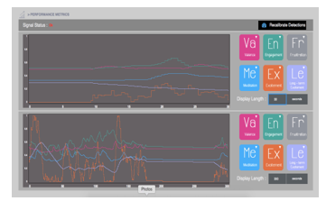
Figure 6. Different signals detected by the Emotiv headset
A 3D cube was displayed, and a training session was available in order to guide the user to move the object either to the left or to the right with his thoughts as shown in Figure 7. The process started by recording the user’s mind when he was not thinking of anything. Then, the user could select an action he prefered to move the object. His thoughts were recorded for the time interval when he was thinking of the object.
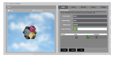
Figure 7. Training session with the 3D cube
Thinking of moving the cube to the left stimulated the hand of the prosthetic arm to close (see Figure 8). However, thinking of moving the cube to the right stimulated the hand to open (see Figure 9).
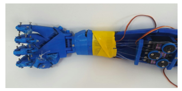
Figure 8. Prosthetic arm – closing hand
Coming up for the scenarios and the algorithms of the arm are one of the things that makes this arm considered as a smart arm. The scenarios simply define the smart reflexes of the arm which can protect the user from the surrounding environment or the people who are communicating with the user. Initially, the arm automatically checks the three sensors (pressure, IR temperature, and proximity). If all of the sensors are in a safe state, the following scenarios can be initiated:
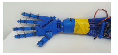
Figure 9. Prosthetic arm – opening hand
Scenario 1: User will be able to initiate brain command and control the arm if all the sensors are in a safe state.
Scenario 2: If the user initiates “Action 1” command, this will enable the handshake. The servomotors in the hand will increment the angle and check if it has the optimum pressure for the handshake. If it reaches it, it will stop automatically.
Scenario 3: If the user imitates “Action 2” command, this will enable the arm to grab a soda can and pour it in a cup. The servo motor in the bicep moves up and stops at a certain degree, then the servo motor in the wrist is rotated so that the soda will be poured in the cup.
On the other hand, if one of the three sensors is not in a safe state, the following scenarios will be taken:
Scenario 4: If the hand holds an object, the temperature sensor, which is embedded within the hand, will measure the temperature. If the temperature is too hot for human skin and reaches the pain threshold, “Action 3” will be automatically initiated. Once Action 3 is initiated a red LED lights up.
Scenario 5: It is the same as the previous scenario, but in this case if the temperature is too hot for the material of the hand itself, “Action 4” is automatically initiated. The servomotors in the hand open the fingers and release the object.
Scenario 6: Here if the proximity sensor which is placed in the back side of the arm reads a distance which is not in the safe range (too close to an object), the servo motors within the shoulder will move the arm forward to keep the arm within a safe range. This is defined as “Action 5”.
Finally the code on the Arduino was updated so that all the individual codes were combined together. The codes for each sensor, the codes for testing the servomotors and the codes for the different gestures based on the input were all put together in a way for the arm to function effortlessly. Within the code, the first thing that was taken into consideration and checked is the sensor network. If the sensors are not in a safe state, they will follow the scenarios as shown previously. Otherwise, the serial port will be checked if it is receiving any data. The serial port is checked because the Arduino communicates with the XBee through a serial connection. If data is being received, it will go through different if statements, each one checking if the input is representing a certain letter. Each letter corresponds either to a raw action (move arm up) or a certain gesture.
The Emotiv EPOC headset has 16 electrodes, which it uses to measure the electromagnetic pulses from the brain. These electromagnetic pulses are created by intentional thoughts, facial expressions and even the mental state of the user. What we will be using for the inputs are the intentional thoughts and the facial expressions.
Before wearing the headset, Saline solution must first be applied to the electrodes. Once the electrodes are damp, they can be connected to the headset. Saline solution is applied in order to increase contact and the quality of the signal read; however, if too much is applied, it could lead to affecting the electrical equipment. Once the user slides the headset on to his head, he/she must insure that the electrodes are placed in the correct position and are in contact with the scalp; this ensures a good signal (green). To get the most accurate output, it is best that all electrodes are green.
The flowchart of the algorithm is shown in Figure 10.
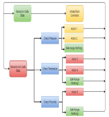
Figure 10. Flowchart of the algorithm
6. Conclusion
The proposed arm hosts state-of-the art technological advancement, communication protocols, control systems, and human interfacing. This gives it great potential in many applications related to the health care field as well as other fields. As long as health care is considered, the idea could be expanded to other body parts as well as to patients having other dysfunctions as nerve damage. On the other hand, many industrial and commercial applications can utilize many features of the proposed arm. Within the health care field, there exists a class of patients who need extra help with their daily lives. This includes elderly people, people under rehabilitation, and people with limited mobility, etc. The proposed arm may be interfaced to a robotic-structure and function as a helper or caregiver to this group of people. It can be programmed to do various functions according to specific patient needs. This may vary from cooking to assistance with bathing or dressing. Another example in the medical field is remote high precision surgical procedures, where surgeons can undergo operations remotely with the aid of the robotic arm. Many industries employ robots in the manufacturing process, many of which can make use of a modified version of the proposed arm. Based on a specific application, this smart arm can be programmed to execute a series of predefined actions, and customized with dedicated sensors, actuators and customized algorithms (such as image and signal processing, gesture and voice recognition etc…). In addition, connecting the arm to the Internet, and making it part of an Internet of Things network (IOT) will increase the performance and productivity of many industry applications. A first prototype is designed, built and was under test. The testing required long training sessions in order first to build a user-dependent library of brain activity patterns, and second to make the user more familiar and comfortable using this hand.
Conflict of Interest
The authors declare no conflict of interest.
- S. W. Hawking, “World report on disability,” World Health Organization, Geneva, Switzerland, 2011.
- NBC News. (2010, March 20). Limb loss a grim, growing global crisis [Online].Available:
http://haitiamputees.nbcnews.com/_news/2010/03/19/4040341-limb-loss-a-grim-growing-global-crisis - M. LeBlanc. (2011, January 14). Give Hope – Give a Hand [Online]. Available: https://web.stanford.edu/class/engr110/Newsletter/lecture03a-2011.html
- C. Moreton. (2012, August 4). London 2012 Olympics: Oscar Pistorius finally runs in Games after five year battle [Online]. Available: http://www.telegraph.co.uk/sport/olympics/athletics/9452280/London-2012-Olympics-Oscar-Pistorius-finally-runs-in-Games-after-five-year-battle.html
- Y. Jeong, D. Lee, K. Kim and J. Park, “A wearable robotic arm with high force-reflection capability,” in 9th IEEE International Workshop on Robot and Human Interactive Communication, Osaka, 2000, pp. 411-416.
- A. Bennett Wilson Jr., B. (n.d.). Retrieved Octobor 17, 2015, from oandplibrary: http://www.oandplibrary.org/alp/chap01-01.asp
- E. Sofge (2012, May 28). Smart Bionic Limbs are Reengineering the Human. [Online]. Available: http://www.popularmechanics.com/science/health/a7764/smart-bionic-limbs-are-reengineering-the-human-9160299
- R. M. Coupland, War Wounds of Limbs: surgical management. Geneve, Switzerland, ICRC, 1993.
- Jerkey. Brain-Controlled Wheelchair [Online]. Available: http://www.instructables.com/id/Brain-Controlled-Wheelchair
- H. Heyrman. Brainwaves [Online]. Available: http://www.doctorhugo.org/brainwaves/brainwaves.html
- S. Sequeira, C. Diogo and F.J.T.E. Ferreira, “EEG-signals based control strategy for prosthetic drive systems,” in IEEE 3rd Portuguese Meeting in Bioengineering, Braga, 2013, pp. 1-4.
- V. Charisis, S. Hadjidimitriou, L. Hadjileontiadis, D. Ugurca and E. Yilmaz, “EmoActivity – An EEG-based gamified emotion HCI for augmented artistic expression: The i-Treasures paradigm,” in Springler-Verlag Berlin Heidelberg, Berlin, 2011.
- T. Beyrouthy, S. K. AlKork and J. A. Korbane, “EEG mind controlled smart prosthetic arm,” in IEEE International Conference on Emerging Technologies and Innovative Business Practices for the Transformation of Societies, August 2016.
- S. K. Al Kork, “Development of 3D finite element model of human elbow to study elbow dislocation and instability,” in ASME 2009 Summer Bioengineering Conference, American Society of Mechanical Engineers, 2009.
- T. Beyrouthy and L. Fesquet, “An event-driven FIR filter: design and implementation,” in 22nd IEEE International Symposium on Rapid System Prototyping (RSP), May 2011.
- C. Heckathorne, “Upper-limb prosthetics: Components for adult externally powered systems,” in Atlas of Limb Prosthetics, H. K. Bowker and J. W. Michael, Eds. Rosemont, IL: Am. Acad. Orthoped. Surg., 2002