Aviation Navigation with Use of Polarimetric Technologies
Aviation Navigation with Use of Polarimetric Technologies
Volume 2, Issue 3, Page No 67-72, 2017
Author’s Name: Arsen Klochan1,a), Ali Al-Ammouri1, Viktor Romanenko2, Vladimir Tronko2
View Affiliations
1Department of Electronics and Computing Techniques, Faculty of Transport and Information Technology, National Transport University, 01010, Ukraine
2Department of Avionic, Educational and Scientific Institute of Air Navigation, National Aviation University, 03058, Ukraine
a)Author to whom correspondence should be addressed. E-mail: varsenchuk@gmail.com
Adv. Sci. Technol. Eng. Syst. J. 2(3), 67-72 (2017); ![]() DOI: 10.25046/aj020310
DOI: 10.25046/aj020310
Keywords: Aircraft, Azimuth of polarization plane, Dielectric plate, Flight trajectory, Fresnel formulas, Mathematical modeling, Measurement method, Navigation
Navigation parameters, Polarimeter, Polarimetric navigation system

Export Citations
The article deals with the problem of increasing the accuracy of determination of aircraft’s navigation flight parameters. Increasing the accuracy and sensitivity of navigation parameters determination will improve the efficiency of air conveyance by optimizing the flight trajectories and reducing the flight time and simultaneously will ensure the sufficient level of air conveyance safety. The main purpose of this article is to develop a polarimetric navigation method for determining the aircraft’s coordinates during flight. This method can potentially increase the accuracy and sensitivity of navigation parameters determination. The article gives a detailed analysis of the existing methods and systems for determination of aircraft’s navigation parameters, their advantages and the sphere of application. Also the polarimetric navigation method and the system for implementing this method are proposed. The system envisages the use of two measurement channels and consists of two main blocks: the radiation unit and the measurement unit. The practical implementation of the proposed navigation method and system includes the development, creation and use of the polarimetric navigation system. The results of system’s mathematical modeling are given and the optimum parameters of the optical channel elements of the proposed system are determined based on these results. Further research in this area envisages the development and creation of the polarimetric navigation system as well as experimental verifications of the concept. Using a high-precision measuring method, such as polarimetric measurement method, to determine the aircraft’s navigation flight parameters will significantly improve the safety and efficiency of the airlines industry.
Received: 06 March 2017, Accepted: 03 April 2017, Published Online: 09 April 2017
1. Introduction
Modern transportation market is characterized by the dynamic development of the airline industry. This is due to increasing mobility of population, development of national and international tourism, increasing enterprise activity and globalization process. According to ICAO statistics annual increase in the volume of regular freight and passenger traffic is observed. Thus, for example, during 2015 [3] there was the increase in the volume of passenger traffic by 7.1% and increase in the volume of freight traffic by 1.7%.The main advantages of aviation operations that distinguish it among other types of transportation are a high speed, high reliability, better safety of cargo, the ability to deliver cargo to remote areas, the shortest traffic routes and others. The vast majority of transcontinental cargo and passenger transportation over long distances is carried out by air. There are main disadvantages of aviation operations such as the high cost, high consumption of materials and high power consumption, dependence on weather conditions.
One of the priorities for increasing the efficiency and safety of air traffic is to ensure effective and overall air navigation services [4]. Improving the quality of air navigation services will optimize routes and reduce the duration of flights. This will reduce some of the above mentioned disadvantages of air transportation. Air navigation services include the air traffic service, the radio-technical support, the aeronautical information service and the meteorological service. This article will focus on radio-technical support aspects of air navigation services.
Radio-technical support should be understood to mean a set of measures aimed at the timely formation of information about air situation and its issuance to aviation’s control point and aircraft’s crews to provide navigation, takeoff and landing of aircraft [5]. Radio-technical support includes providing communication, navigation and surveillance. This article will focus on providing navigation of the aircraft’s flight.
Air navigation (Aeronavigation) is the realm of science about the methods and means of driving the aircraft and determination of its movement parameters during the flight within the atmosphere. The aircraft’s flight includes several main stages, such as, takeoff, climb, route flight, landing approach, landing and others. During the flight, the following navigational tasks are performed: programming of flight trajectory; determining the coordinates of the aircraft in space; determining the vectors of air speed, ground speed and wind speed; determining the flight time to point of call, turning points; determining maneuver in the horizontal and vertical planes during flight, approach, landing and other tasks. Accurate and timely determination of aircraft navigation parameters at each stage is a prerequisite for safe and efficient air transportation.
Aircraft’s navigation parameters include parameters and their derivatives, which describe orientation, location and movement of aircraft in space and around center of mass. There are the main navigational parameters defined during the flight such as coordinates (geographical, polar), height (absolute altitude, height above ground, true height), heading (magnetic, true, great-circle), speed (indicated, airspeed, ground), attitude (roll, pitch and yaw angles) and others.
One of the promising directions to improve the efficiency of air transportation is the concept of free flight. This concept involves transferring operating choice of the route trajectory, flight speed and profile to aircraft crews [6].This will allow using airspace more rationally and flexibly. Applying this concept can increase efficiency and provide annual savings of several billion dollars by reducing fuel consumption and flight time. Applying of this concept involves the compacting of the flow of air transport in airspace. This, in turn, requires improving the accuracy of determination of the coordinates and position of aircraft in air space, as well as providing early warning about possible conflicts to ensure the necessary level of safety.
2. Problem Statement
The dynamic development of the airline industry, the air traffic volume growth and implementation of air traffic management concepts «Free Flight» lead to the necessity for compacting the flow of air transport in airspace and lead to potential reduction in air transportation safety because of aircraft collision at the critical density of aircraft in the air space. Improving safety with air transport flow compacting is possible by increasing the accuracy of determination of the aircraft’s coordinates and by predicting aircraft motion trajectory for the near future. The analysis of the motion trajectories of aircraft which are in locally restricted space will allow providing air traffic regulation and safe deconfliction of aircraft in the airspace. Thus, there is a need to develop new or improve existing methods for determining the coordinates of the aircraft to ensure improvement of measurement accuracy. It is critical to improve measurement accuracy of aircraft coordinates in locally restricted space: in the zone of the airport, around turning point, near the intersection zone of air-route and in other zones of airspace with a high density of aircraft.
3. Review
To determine navigation parameters, different technical means which can be divided into autonomous and non-autonomous systems are used. The non-autonomous navigation systems define navigation parameters by using information which coming on board from outside. The autonomous navigation systems are characterized by the use of onboard equipment for navigation parameters determination.
All navigation technique depending on their physical principles of action can be divided into 5 main groups: geotechnical, inertial, radio, astronomical, lighting. Each of these groups has certain operating peculiarities and is used to define aircraft’s leg.
Geotechnical navigation means are based on the different physical properties of the Earth and its atmosphere, which include the gravity force, Earth’s magnetism and the earth magnetic field, terrain, pressure change with flight altitude changing, air velocity, thermal properties of the Earth and others. This group of navigation technical means refers to autonomous navigation systems and is characterized by low accuracy and sensitivity. This group includes magnetic and gyromagnetic compasses, magnetometers, gravitometers, a barometric altimeter, an air speed meter, correlation-extreme navigation systems and others. This group of navigation technical means was widely used at the beginning of aviation development, and now they are used as emergency devices.
Radio navigation means are based on the physical properties of artificial electromagnetic waves that propagate in space. This group of means refers to non-autonomous navigation systems: the source of radio waves (radio beacon) is needed for their work. This group of means is characterized by high precision work in any weather conditions, at any time of the day, and at different distances. This group includes a short range radio navigation system, a long range radio navigation system, the VOR system, the DME system, a radio altimeter and others. Radio navigation means are widely used in modern aircraft in different stages of flight, to perform various tasks.
Astronomical navigation means are based on the use of objective laws of relative position and the Earth’s motion relative to the Sun, the Moon and other celestial bodies. This group of navigation technical means refers to non-autonomous navigation systems: visibility of celestial bodies is needed for their work. This group of means is characterized by high accuracy and is used exclusively for navigation tasks. Equipment of astronomical navigation means is used as an additional information source of aircraft position during flight over the ocean and in the North and South Poles. This group includes astronomical compasses, sextants and others.
Inertial navigation means are based on measuring of angle rate and linear accelerations caused by the action of non-gravitational force (engine thrust, atmospheric effect, lift component, control force and others). This group of means refers to autonomous navigation systems. Modern inertial means are characterized by relatively high accuracy and sensitivity, the accumulation of errors over time, the relatively small weight and size. This group includes fiber optic gyros, ring laser gyros, MEMS-gyros, attitude and heading reference systems, inertial navigation systems and others. This type of navigation means is widely used in modern aircraft in different stages of flight, to perform various tasks.
Lighting and visual navigation means are intended to marking of visual cues and provide ground-based aircraft navigation. This group of means refers to non-autonomous navigation systems: for their work is needed earth-based system for marking of visual cues. Means of this group is mainly used at leg of takeoff and landing. This group includes light beacons, searchlights, laser instrument landing systems of direct vision, laser instrument landing systems on the dispersion effect and others.
The current stage of aerotechnics development is characterized by integrated utilization of navigation technical means with different physical principles. It permits to reduce the measurement error of navigation parameters significantly and reduce the adjustment time of navigation system.
Inertial and radio navigation systems and methods are widely used to determine navigation parameters during end route flight. Inertial navigation systems allow obtaining information about linear and angle accelerations on aircraft’s board. Onboard system determines the angle of turn and covered distance in some system of coordinates, as well as calculates aircraft’s navigation parameters, such as coordinates, heading, attitude, altitude, speed and others. Radio navigation systems provide determination of aircraft’s coordinates by measuring distance and azimuth to radio beacon. The holistic use of inertial and radio navigation systems permit to increase the accuracy of determining the navigation parameters.
Consider radio navigation systems in more detail. . According to the measured navigation parameter radio navigation systems are divided into the azimuth-measurement navigation system, range-measurement navigation system, rho-theta navigation system, differential-range measurement navigation system and others.
The systems which provide the navigational information about the distance to the radio beacon on board of the aircraft refer to the range measurement navigation systems. Using this type of navigation systems allows determining aircraft coordinates by the distance to three DME-beacons or the distance to two DME-beacon and altitude.
Azimuth-measurement radio navigation systems are the systems which provide the navigational information about relative angular position of aircraft and radio beacon on board of the aircraft. Using this type of navigation system allows determining aircraft coordinates by the azimuths of two VOR beacons and altitude.
The systems that provide the navigational information about relative angular position of the aircraft and radio sources and about the distance to the radio beacon on board of the aircraft are defined as rho-theta navigation system. Using this type of navigation system allows determining aircraft coordinates by the azimuth and distance to radio beacon and altitude.
The differential-range measurement navigation systems are the systems that provide on board of the aircraft the navigation information about the location of aircraft by determining the difference of the distances to several radio navigation points. To determine the coordinates of the aircraft, it is necessary to have three (four) independent differences of the distances to two (three) beacons.
So to perform navigation tasks during the flight route the most widely used radio and inertial navigation means. The radio navigation means characterized by high precision work in any weather conditions, at any time of the day, and at different distances, but needs availability of radiowaves source – radio beacon. The inertial navigation means are autonomous and characterized by relatively high accuracy and sensitivity, the relatively small weight and size, but they accumulate the errors over time. Integrated utilization of inertial and radio navigation systems permit to increase the accuracy of aircraft’s navigation parameters determining.
4. Problem Solution
Optical measurement methods are widely used in various fields of science and technology. Application scope of optical measurement methods has expanded significantly in recent years. This is due to their advantages. Optical measurement methods have the following advantages: noncontact measurement, non-destructive testing, high speed of measurements, high measurement accuracy and sensitivity, and others. One of the application directions of optical measurement methods for determining the aircraft’s coordinates is the use of the optical gyroscopes: fiber optic gyroscopes and ring laser gyroscopes. Their operation principle is based on the Sagnac effect. This effect consists in the change of the phase difference of two oppositely directed light waves, which propagate in a closed loop at its turn around a normal axis. Optical gyroscopes are autonomous means and refer to inertial navigation means. They are characterized by high accuracy, sensitivity and stability, relatively small gyro drift – 0,001 degrees per hour. The disadvantages of ring laser gyroscopes include high power, the complexity of their production technology, relatively large mass and dimensions. The disadvantages of fiber optic gyros include inverse scattering, effect of temperature, vibration, magnetic and electric fields on the quality of their work.
One of the most sensitive optical measurement methods is polarimetric measurement method. It allows measuring the azimuth plane polarization with accuracy 0,0005° [7]. Polarimetric measurement methods involve measuring the polarization properties of radiation after interaction of polarized radiation with the objects: the degree of polarization, azimuth plane of polarization, ellipticity and others. The use of polarimetric measurement methods to solve navigation problems is possible through the use of an isotropic dielectric plane-parallel plate in the optical channel of measurement. The dielectric plate rotates the plane of polarization of the incident radiation depending on his angle of incidence.
This paper is an extension of work originally presented in IEEE 4th International conference « Methods and Systems of Navigation and Motion Control (MSNMC) » [8]. This article continues studying the issue of using polarimetry in aircraft navigation systems and is aimed at a wider and more detailed examination of the polarimetric technology possibility to solve aviation navigation tasks. Polarimetric techniques are understood to mean the totality processes of collection, accumulation, processing, transmission, storage and display of information. They use polarimetric methods and devices to obtain basic information about the object. This article proposes the polarimetric navigation method and system, which implements this method. The operation principle of the method is based on Fresnel’s formulas. The proposed method and system are based on the use of physical properties of artificial electromagnetic waves in the optical band, which propagate in space. The polarimetric navigation method and system are classified as non-autonomous and in accordance with the classification above they can be attributed to radio navigation means.
Rotating the polarization plane of polarized radiation after falling on isotropic planar dielectric plate with weakly absorbing material is explained by various transmittance and reflectance for p- and s-polarized beam components, which are described by Fresnel’s formulas. Studies, presented in [1] and [2], confirm this statement and show that at falling of linearly polarized beam on the dielectric plate the reflected and refracted beams will also be linearly polarized, and the angle of polarization plane will depend on the angle of incidence.
The values of azimuth of polarization plane for the reflected and refracted beam that has passed through the two faces of the plate can be determined by the following formulas: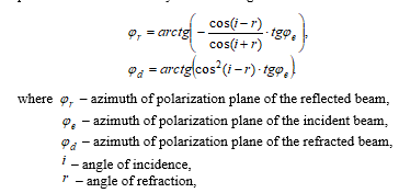
Thus, when polarized radiation falls on the isotropic dielectric plate, the polarization plane of the refracted beam, reflected beam and beam passing through the two faces of the plate rotates. The azimuth rotation of polarization plate depends on the incidence angle of radiation and the azimuth of polarization plane of the incident beam.
The use of polarimetric technologies to solve the aeronavigation tasks is as follows. The emitter, which is located on navigation beacon, emits linearly polarized radiation with a certain dispersion aperture in the vertical plane and the minimum dispersion aperture in the horizontal plane. The polarization plane of radiation rotates simultaneously with the rotation of radiation diagram. The meter located on board of the aircraft receives radiation from the navigation beacon, measures the polarization plane azimuth of the beam that has passed through the two faces of the plate and determine the angle of incidence and polarization plane azimuth of the incident beam. This polarization plane azimuth of the incident beam is directly associated/ connected with the navigation beacon bearing and angle of incidence depends on the relative navigation beacon bearing and distance to it, as well as pitch angle, yaw angle and altitude of the aircraft.
Consider the block diagram of the optical measurement channel shown in Fig. 1.
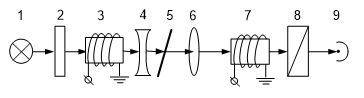
Figure 1. Block diagram of the optical channel
Radiation source 1 is intended to emit unpolarized light. The optical filter 2 is designed to filter radiation in order to highlight a certain wavelength. Faraday cell 3 is designed to polarize radiation and to rotate its plane of polarization according to the law of diagram rotation of beacon radiation. Scattering lens 4 is designed to dissipate polarized radiation with defined aperture dispersion. The dielectric plate 5 is designed to rotate the plane of polarization depending on the angle of incidence and polarization plane azimuth of the incident beam. It provides primary information about angle of incidence and polarization plane azimuth. Focusing lens 6 is designed to focus the polarized beam after dielectric plate on modulator 7. Analyzer 8 is designed to determine the plane azimuth of polarization radiation, which has passed through the dielectric plate. Photodetector 9 is designed to convert the intensity of radiation incident on it into an electrical signal. The resulted electrical signal is sent to the measurement unit for determining of polarization plane azimuth and incidence angle of radiation.
Accuracy measurement is defined by the relation of a signal to noise. The relation of a signal to noise for photodetector has the following appearance [7]: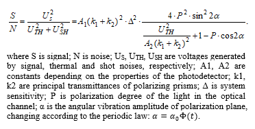
Using the polarimetric techniques to solve aeronavigation problems anticipates the use of polarimetric navigation system, which consists of two main units: radiation unit and measurement unit. Radiation unit is set on the beacon and designed to emit polarized beam with fixed value of polarization plane azimuth. At that the polarization plane azimuth depends on the direction of radiation. Measurement unit is set on the onboard and designed to measure the polarization plane azimuth of the passed beam and calculate navigation beacon bearing. Radiation unit has two channels and provides radiation of two linearly polarized beams with different wavelengths and polarization plane azimuths. Dependence of the polarization plane azimuth in the first and second channels (ϕ1, ϕ2) on radiation azimuth (θ) of the navigational beacon is shown in Fig. 2. Radiation unit consists of two identical channels, each of which is configured to corresponding channel of radiation unit.
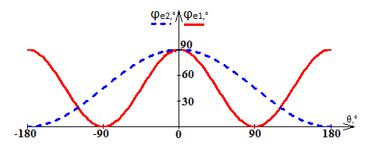
Figure 2. Dependence polarization plane azimuth on radiation station azimuth in the first and second channel
The block-diagram of one channel of polarimetric navigation system is shown in Figure 3. One channel of polarimetric navigation system includes radiation unit 1, measurement unit 2 and propagation medium 11. Unit 1 emits the polarized beam with certain polarization plane azimuth that passes through the propagation medium 11 and falls to the measurement unit 2 where the calculation of navigation beacon bearing takes place.
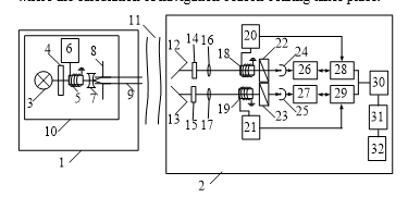
Figure 3. Block diagram of one channel of polarimetric navigation system
One channel of the radiation unit includes radiation source 3; monochromator 4; Faraday cell 5; sound generator 6; scattering lens 7, slit diaphragm 8. Both radiation channels are placed on the platform 10, which rotates. Monochromator 4 is designed to filter the incidence beam and miss out the wavelength on which the appropriate channel of measurement unit is tuned. Faraday cell 5 is designed for polarizing the beam and rotating its plane of polarization. Sound Generator 6 is intended to form control signals to the Faraday cell 5. Scattering lens 7 and a slit diaphragm 8 are designed for scattering plane-polarization radiation in the vertical plane with minimal divergence radiation angle in the horizontal plane. The platform 10 rotates around a vertical axis at constant frequency and provides changing the radiation direction of the beam 9. The beam polarization plane and platform rotate rotates simultaneously. This ensures communication of polarization plane azimuth and the radiation station azimuth. Two measurement channels differ by rotation frequency of the polarization plane: in the first channel it is equal to the speed of platform rotation, while in the second channel it is equal to the half of the platform rotation frequency.
The channel of measurement unit consists of planar dielectric plates 12 and 13, which are designed to rotate the polarization plane depending on the angle of incidence and polarization plane azimuth of the incident beam, it provides getting primary information about incidence angle and polarization plane azimuth; optical filters 14 and 15, which are designed to filter the incidence beam and miss out the wavelength on which the appropriate channel of radiation unit is tuned; focusing lens 16 and 17, which are designed to focus the radiation on the Faraday cell 18 and 19; Faraday cell 18 and 19, which are designed to modulate polarized radiation in an alternating magnetic field; sound generators 20 and 21, which are designed to form the control signals which are transmitted for Faraday cells 18 and 19; analyzers 22 and 23, which are designed to determine the polarization plane azimuth; photodetectors 24 and 25, which are designed to convert polarization plane azimuth into an electrical signal; narrow-band amplifiers 26 and 27, which are designed for amplifying electrical signal; synchronous detectors 28 and 29, which are designed to increase the measurement sensitivity and provide measurement “on zero signal”; microcontroller 30, which is designed for processing measurement results; storage unit 31, which is designed for collecting and storing measurement results; calculator 32, which is designed to perform mathematical calculations.
5. Result of Research
The paper represents the azimuth-measurement polarimetric method for determining the coordinates of the aircraft and the navigation system that implements the proposed method. Proposed navigation system allows measuring the relative angular position of the aircraft and navigation beacon. At that, aircraft’s coordinates are determined by the azimuths of two beacons and altitude. The system consists of two channels. The polarization plane azimuth and incidence angle of radiation are defined in each channel. The value of polarization plane azimuth of incidence radiation in two channels determines the airplane bearing. The measured value of the incidence angle may be used in determining the altitude, pitch angle and station bearing.
In the process of mathematical modeling the dependence graph of the polarization plane azimuth of the refracted beam on incidence angle for different values of polarization plane azimuth of the incident beam (Fig. 4), the dependence graph of the measurement sensitivity on polarization plane azimuth of the incident beam (Fig.5), the dependence graph of the polarization plane azimuth of the refracted beam on the polarization plane azimuth of the incident beam for different values of the incidence angle (Fig. 6) were created. To determine the optimal incidence angle we created the dependence graphs of measurement sensitivity and refracted beam intensity on incidence angle on the same graph (Fig. 7). The incidence angle value of the intersection point is optimal incidence angle.
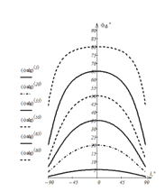
Figure 4.Dependence graph of the polarization plane azimuth of refracted beam on incidence angle
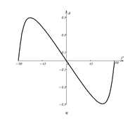
Figure.5 Dependence graph of the measurement sensitivity on polarization plane azimuth of the incident beam
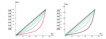
Figure 6. Dependence graphs of the polarization plane azimuth of the refracted beam on polarization plane azimuth of the incident beam
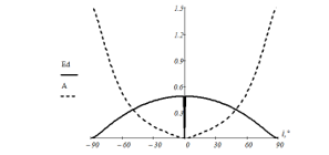
Figure 7 – Dependence graph of measurement sensitivity and refracted beam intensity on incidence angle
After analyzing the dependence graph of the polarization plane azimuth of refracted beam from incidence angle (Fig. 4), we conclude that the relationship is symmetric about the y axis and depends on the polarization plane azimuth of the incident beam. After analyzing the dependence graph of the measurement sensitivity on polarization plane azimuth of the incident beam (Fig. 5), we conclude that the relationship is symmetric about zero and has extremes. The graph shows that the highest sensitivity value provides polarization plane azimuth ϕe= ± 68°. After analyzing the dependence graph of the polarization plane azimuth of the refracted beam on polarization plane azimuth of the incident beam (Fig. 6), we conclude that the relationship is nonlinear and depends on the incidence angle. At that, the sensitivity of the measurement increases with the increase of the incidence angle. After analyzing dependence graphs of measurement sensitivity and refracted beam intensity on incidence angle on the same graph (Fig. 7), we conclude that the optimal incidence angle (i) equal i= ± 52,5°. The optimal incidence angle is provided by installation of dielectric plate at an angle to the horizontal plane. Due to the fact that one measurement channel unit has two dielectric plates, it is proposed to establish one plate at an angle of 52.5 ° to the vertical plane and the second 52.5° angle to the horizontal plane.
6. Conclusions
The article deals with the existing methods for determining navigation parameters and the proposed azimuth-measurement polarimetric method for determining the coordinates of the aircraft. This method can potentially increase the accuracy and sensitivity of determining the navigation parameters. Also in the article the measurement system that implements this method is proposed. The proposed method and system can be used with azimuth-measurement and rho-theta navigation system for determining the aircraft’s coordinates.
Distinction between the proposed system and optical gyroscopes lie in different principles of action: optic gyroscopes are autonomous means and polarimetric system is non-autonomous means, as well as lie in various physical operation principles: optical gyroscopes are based on the Sagnac effect and polarimetric navigation system is based on the Fresnel’s formulas. Integrated utilization of optical gyroscopes and means of polarimetric navigation system will greatly increase the accuracy, sensitivity and reliability of information about aircraft’s navigation parameters of flying.
The article also shows the results of mathematical modeling of the measurement channel. Optimal polarization plane azimuth of the incident beam and optimal incidence angle of radiation were determined during mathematical modeling. Calculations can be applied in the development and implementation of polarimetric navigation system. The practical implementation of the proposed method is to create a polarimetric navigation system and requires additional theoretical and practical research. This article reflects results of one theoretical research stage of the possibility to use the polarimetric technology for solving air navigation tasks.
- Азам Р., Башара Н. Эллипсомерия и поляризованный свет, Мир, 1981.(R. Azzam, N. Bashara, Ellipsometry and Polarized Light, Mir, 1981). (in Russian)
- Поль Р. В. Оптика и атомная физика, Физико-математическая литература, 1966. (R. Pohl, Optics and Nuclear Physics, Physical and Mathematical Literature, 1966 ) (in Russian)
- Annual Report of the ICAO Council: 2015
- Air Navigation Report 2016 Edition, 2016
- Правила організації радіолокаційного забезпечення польотів державної авіації України (Organizational radar support regulations of flight of Civil Aviation of Ukraine.). (in Ukrainian)
- В. І. Чепіженко, В. О. Волкогон, “Роль сучасних концепцій трансформації CNS/ATM систем у забезпеченні автономних польотів повітряних кораблів”, Actual Problems of Automation and Information Technologies, 19, 112–120, 2015. (V. Chepizhenko, V. Volkogon “The role of modern concepts of system transformation CNS / ATM to provide
autonomous flight of aircraft”, Actual Problems of Automation and Information Technologies, 19, 112–120, 2015) (in Ukrainian) - Asanov, V. Rogozhin, A. Skrypets, V. Tronko “Estimation of accuracy characteristics of onboard vertical meters based on photopolarimetric metod”. Electronics and control systems.. 3 (34), 46–50, 2012.
- Klochan, A. Al-Ammouri V. Romanenko, V. Tronko “Aplication of polarymetry in aviation navigation systems” in IEEE 4th International conference «Methods and Systems of Navigation and Motion Control (MSNMC)», Kyiv, Ukraine, 2016.