Feedback device of temperature sensation for a myoelectric prosthetic hand

Adv. Sci. Technol. Eng. Syst. J. 2(3), 41–47 (2017);
 DOI: 10.25046/aj020307
In this study, a control system of a feedback device of temperature sensation for myoelectric prosthetic hand users was improved. The device is mounted on a user’s upper arm in contact with the skin, and transfers the temperature sensation in the upper arm corresponding to the temperature detected by the temperature sensor at the fingertip to the user. However, since the feedback device developed in the previous study was controlled in an open loop system, it was difficult to maintain the temperature for a long period. To solve this problem, a closed loop control system was constructed for the feedback device by using a PID controller. In addition, in order to verify the performance of the feedback device controlled in the closed loop control system, performance evaluation experiments were performed. As a result, the sufficient capability of the feedback device controlled in the closed loop control system was indicated. Finally, temperature identification experiments were performed based on psychophysical method to verify an effectiveness of the feedback device. As a result, the difference threshold of the feedback device of temperature sensation, 0.62°C was obtained.
1. Introduction
A myoelectric prosthetic hand is an electrically driven artificial hand in which the intended motion is identified and the movement is controlled based on biosignals generated when muscles are moved. However, myoelectric prosthetic hand users are unable to feel sensations when they touch an object using a prosthetic hand. Therefore, investigation of the functions that provide sensation feedback to the user is required. It is shown that sensory feedback is important for improvement in proficiency level of a myoelectric prosthetic hand [1].
Recent researches focused on developing a feedback device of sensations for myoelectric prosthetic hand users. These included our previous study [2] in which a feedback device of force sensation was developed. In this mechanism, when the myoelectric prosthetic hand held an object, the belt of the device was wound by a motor and tightened the operator’s upper arm. This enabled the user to obtain a force sensation. Additionally, the user could feel a difference in the object hardness by changing the winding speed of the belt.
In our previous study [6], a feedback device of temperature sensation was developed by using a Peltier element to perceive the object temperature when the user touches objects by a prosthetic hand. The object temperature is measured by a temperature sensor attached at fingertip of the prosthetic hand. However, the temperature measurement required several tens of seconds. Therefore, a temperature prediction algorithm was proposed to shorten the measurement time. The study [4] examined a device that transmits a temperature difference between skin temperature of cut section and object temperature. However, the temperature sensation differs at each body site. Therefore, the feedback device developed in our study transfers temperature sensation in the upper arm corresponding to the temperature detected at the fingertip of the prosthetic hand. To this end, an experiment to examine the difference in the temperature sensation felt by the fingertip and that felt by the upper arm was performed, and the feedback device reproduces the temperature sensation felt by the fingertip to the upper arm based on the result of the experiment. Furthermore, an identification experiment for temperature was performed to verify the effectiveness of the feedback device. However, the feedback device developed in previous study was controlled in an open loop system. Therefore, it was difficult to maintain the temperature using this control system.A study [3] also reported a feedback device using vibrations. The device changed the vibration intensity based on the size of the detected force. Another study [4] reported a device that perceives the temperature when touched by a myoelectric prosthetic hand using a hot and cold pad. This device obtains the temperature difference between an object and the user’s skin temperature by the changes in the temperature of the hot and cold pads. A study [5] examined transfer of temperature sensation using the Peltier element.
This paper is an extension of work originally presented in 2016 International Conference on Advanced Mechatronic Systems [6]. The key changes from the conference paper are summarized as follows.
In this paper, a closed loop control system was constructed to enhance the performance of the feedback device. In addition, to improve the operability of the myoelectric prosthetic hand, a new myoelectric prosthetic hand was built. Then, performance evaluation experiments were performed to verify the performance of the feedback device controlled in the closed loop control system using the new myoelectric prosthetic hand. Furthermore, psychophysics tests were conducted to measure the difference threshold of the feedback device in terms of the temperature difference.
2. Feedback Device of Temperature Sensation
2.1. Peltier Effect and Seebeck Effect
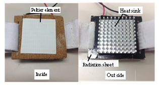
Exothermic and endothermic reactions occur when an applied current flows through a junction between two conductors. This phenomenon is called the Peltier effect. The Peltier element is an electronic device that changes surface temperature on the basis of the Peltier effect. It enables both cooling and heating by applying a voltage, and temperature can be adjusted by regulating the voltage. The feedback device has a Peltier element, and transfers the temperature sensation to the user. The Peltier element used in this study is “TEC1-12708” Peltier element made by HB Electronic Components.
In contrast to the Peltier effect, the Seebeck effect is a phenomenon that generates a voltage by providing a temperature difference to a conductor. When the temperature difference is provided to the conductor, voltage that is proportional to the temperature difference is generated due to the Seebeck effect. This principle is used to measure temperature. A thermocouple is a temperature sensor that uses the Seebeck effect. In this study, a K type “AD-1214” thermocouple manufactured by T & D Corporation was used as the temperature sensor.
2.2. Outline of Feedback Device
Figure 1 shows the feedback device of temperature sensation (Hereafter, FB device) developed in our study.
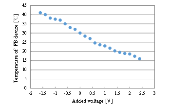
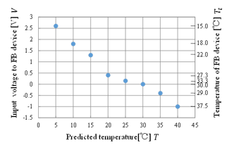
When the FB device is used for a long period, there is a possibility of high-temperature due to the accumulated heat. Hence, the continuous operating time of the FB device controlled in an open loop control system was limited to 5 s. Figure 2 shows relationship between the applied voltage and the temperature produced by the FB device.
The FB device enables refrigeration of surface temperature to a minimum of 15°C for 5 s. In addition, when the FB device increases the temperature, it enables heating exceeding 50°C. However, the temperature of the FB device was limited to 40°C for safety considerations.
3. Temperature Prediction and Temperature Sensation Investigation
After contact with the object, it takes several tens of seconds until the measured value settles. Thus, the temperature sensor needs a long time for measuring the temperature. Consequently, a temperature prediction was performed to shorten the measurement time.
3.1. Temperature Prediction Algorithm
Let y(t) denote a sensor output and u(t) denote an amount of temperature variation, and let relationship between y(t) and u(t) be given by the following equation in transfer function expression: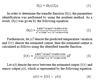
The predicted temperature variation is updated by using as follows in each sampling period.![]()
where is the predicted temperature variation one step before and denotes an updated predicted temperature variation. In addition, K is an arbitrary constant, which was chosen as K=70 in this study, since noise was comparatively low and the reaction time was fast when the temperature prediction was performed.
Let T denote the predicted temperature and denote the room temperature, then the predicted temperature is given by the following equation.![]()
The predicted temperature is updated to reduce the error when the sensor detected a change of the temperature, thus the temperature when reached to the equilibrium state is given by Equation (6). As a result, the sensor can detect the temperature of the object in a short time.
3.2. Verification of Temperature Prediction Algorithm
In order to verify the effectiveness of the proposed temperature prediction algorithm, an experiment to investigate the behavior of the temperature prediction when the touched object was changed to an object with a different temperature during the temperature prediction was performed. When the sensor touched an object with a temperature of 20°C after touching an object with a temperature of 30°C under the room temperature of 25°C, the temperature was predicted by using the temperature prediction method. Figure 3 shows the result of the temperature prediction.
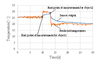
The results showed that it is possible to perform the temperature prediction even when an object with a different temperature was touched during the temperature prediction.
3.3. Purpose of Temperature Sensation Investigation
It is difficult for the FB device to reproduce the low temperature. As shown in Figure 2, the FB device cannot reproduce a temperature of lower than 15°C. However, the temperature sensations of an individual differ at each body site. For example, there is difference between the temperature sensations when an object with the same temperature is touched with a finger or with the upper arm. Therefore, an investigation of temperature sensation was performed, and a temperature that corresponds to the temperature at which an object was touched with a finger was determined as feedback temperature to the upper arm.
3.4. Method and Result
In order to investigate the difference in the temperature sensation between the fingertip and the upper arm, an experiment was performed in the following procedure using water from temperatures ranging from 5°C to 40°C for each 5°C. The details of the procedure of this experiment are addressed in the literature [6].
Table 1 shows the result of the temperature sensation investigation performed for 7 healthy subjects in their 20s.
Table 1: Result of temperature sensation investigation
|
|
Subject | Temperature (Fingertip) [℃] | |||||||
| 5 | 10 | 15 | 20 | 25 | 30 | 35 | 40 | ||
| Temperature (upper arm) [℃] | A | 15 | 18 | 22 | 27 | 29 | 30 | 34 | 37.5 |
| B | 15 | 18 | 22 | 28 | 29 | 30 | 33 | 37.5 | |
| C | 15 | 18 | 22 | 28 | 29 | 30 | 33 | 37.5 | |
| D | 15 | 18 | 22 | 27 | 29 | 30 | 33 | 37.5 | |
| E | 15 | 18 | 22 | 27 | 29 | 30 | 34 | 37.5 | |
| F | 15 | 18 | 22 | 27 | 29 | 30 | 33 | 37.5 | |
| G | 15 | 18 | 22 | 27 | 29 | 30 | 33 | 37.5 | |
| Ave. | 15 | 18 | 22 | 27.3 | 29 | 30 | 33.3 | 37.5 | |
Based on these results, the FB device is controlled to reproduce the temperature experienced by the upper arm which is equivalent to the temperature experienced by the fingertip. Thus, the temperature sensation which should be reproduced to the FB device is determined by the temperature prediction at the fingertip. However, the temperature of FB device is not changed when the prosthetic hand touched an object at 30°C. This is because the temperature of FB device is approximately 30°C at normal temperature.
temperature at the fingertip and the input voltage to the FB device are approximated as shown in Equations (7) and (8) respectively, by using the least-squares method.

4. Temperature Identification Experiment
4.1. Purpose and Equipment
The FB device transmits the temperature sensation corresponding to the predicted temperature of the object which was touched by the fingertip of the myoelectric prosthetic hand to the user’s upper arm. In order to verify the effectiveness of the developed FB device, the temperature identification experiment was performed using a myoelectric prosthetic hand developed in the literature [7].
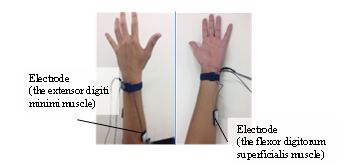
The myoelectric prosthetic hand needs three types of operations in the experiment, namely bending the finger to touch the object, maintaining the posture, and releasing the finger. To distinguish these operations, electrodes were stuck on the flexor digitorum superficialis muscle and the extensor digiti minimi muscle to measure surface electromyogram (SEMG). The flexor digitorum superficialis muscle is used to flex the fingers, and the extensor digiti minimi muscle is used to extend the fingers. Figure 4 shows the positions where the electrodes were stuck on.
The motion of user’s hand is identified based on the measured SEMG and the myoelectric prosthetic hand is controlled by using an operation method proposed in the study [8].
4.2. Method of Experiment
The subjects executed the identification of the temperature transmitted by the FB device. In the experiment, another Peltier element which is different from that of the FB device was used as the object touched by the fingertip of the prosthetic hand. The following five variations in temperature were employed: hot (approximately 40°C), lukewarm (approximately 35°C), not much (25°C–30°C), a little cold (approximately 20°C), and cold (approximately 15°C).
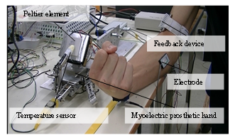
The temperature identification experiment was performed in the following way. The temperature of the object (Peltier element) is randomly selected from the five variations, and the temperature of the object is adjusted to become the selected temperature. The subject operates the myoelectric prosthetic hand to touch the object. Then, the temperature prediction is performed and the voltage calculated from Equation (8) on the basis of the predicted temperature is applied to the FB device. Based on the corresponding temperature sensation reproduced by the FB device, the subject identifies the temperature of the object from the five variations. The experiment was executed for 10 subjects. The experimental environment is shown in Figure 5.
4.3. Result
Table 2 shows the success rates of temperature identification for each subject, and Table 3 shows the success rate of temperature identification for each presented temperature.
Table 2: Result of the temperature identification
| Subject | Success rate of identification [%] |
| A | 90 |
| B | 80 |
| C | 100 |
| D | 90 |
| E | 70 |
| F | 100 |
| G | 80 |
| H | 100 |
| I | 90 |
| J | 80 |
| Average | 88 |
Table 3: Success rates for each temperature
| Presented temperature [°C] | Success | Failure | Success rate of identification [%] |
| 40 | 17 | 0 | 100 |
| 35 | 23 | 5 | 85.2 |
| 25–30 | 9 | 1 | 90 |
| 20 | 22 | 4 | 84.6 |
| 15 | 17 | 2 | 89.5 |
The results show that the average success rate for 10 subjects is 88%. In addition, the success rate of each presented temperature exceeded 84%. The above results revealed that the difference in temperature can be recognized with high accuracy. The causes for the failure identification include the failure of the temperature prediction and the individual differences of the sensation of each subject.
5. Closed Loop Control System
5.1. Construction of the Control System
The FB device developed in the previous study is controlled in an open loop system, in which the constant voltage through Equation (8) computed from the predicted temperature is applied to the FB device. Hence, it is difficult to maintain the temperature using this control system, because if the voltage is continuously provided to the FB device the temperature keeps increasing or decreasing. Therefore, the continuous operating time of the FB device was limited to 5 s.
To solve this problem, a closed loop control system was constructed. To this end, a temperature sensor which is the same type as one attached at the fingertip of the prosthetic hand was additionally attached on the surface of the Peltier element of the FB device. The target temperature in the upper arm corresponding to the predicted temperature at the fingertip of the myoelectric prosthetic hand is determined by Equation (7). Then, the input voltage to the FB device is determined by a PID controller. The PID gains were determined by trial and error, and chosen as , and .
In order to verify the validity of the closed loop control system with PID controller, sudden change in temperature when the target temperature is decreased from 40°C to 15°C was examined. The transition of the temperature of the FB device and the input voltage to the FB device are shown in Figure 6.

As shown in Figure 6, the constructed closed loop system enabled the adjustment of the presenting temperature of the FB device according to the temperature change and also enabled a long time continuous operation of the FB device.
6. Performance Evaluation Experiments
6.1. Purpose and Equipment
In order to verify the performance of the FB device controlled in the closed loop control system, an evaluation experiment was performed.
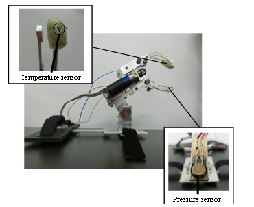
To improve the operability of the myoelectric prosthetic hand, a new myoelectric prosthetic hand was designed and built by imitating the commercial prosthetic hand, which is shown in Figure 7. The temperature sensor was attached to the silicone finger installed on the fingertip of the index finger of the myoelectric prosthetic hand, and the pressure sensor was attached to the fingertip of the thumb of the prosthetic hand. Thus, when the prosthetic hand holds an object, temperature value of the object and grasping force of the finger are obtained. The new myoelectric prosthetic hand was used in this experiment.
6.2. Method of Experiment
The experiment was performed in the following procedure. In this experiment, the following four variations in temperature were employed: approximately 40°C, approximately 35°C, approximately 15°C, and approximately 5°C.
- The temperature of the object (Peltier element) is adjusted to become the selected temperature.
- The temperature of the object is recorded and the real value of the target temperature in the upper arm is calculated through Equation (7) from .
- The object is touched by the fingertip of the myoelectric prosthetic hand.
- The temperature prediction is performed and the target temperature corresponding to the predicted temperature is calculated through Equation (7).
- The temperature of the FB device is controlled by using the closed loop control system.
- The temperature of the FB device and the target temperature corresponding to the predicted temperature are recoded.
- The error between the target temperature and the real value (prediction error ), and the error between the target temperature and the temperature of the FB device (control error of the FB device ) are recorded for 10s.
The above procedure was repeated 5 times for each temperature.
6.3. Result
Table 4 shows the result of the performance evaluation experiment.
From the experimental result, a maximum error of 3.43°C was observed between the target temperature and the real value , and a maximum error of 2.86°C was observed between the target temperature and the temperature of the FB device . In addition, the overall average of the prediction error and control error of the FB device for 10s were 1.09°C and 0.61°C, respectively. From this result, it is considered that the FB device controlled in the closed loop control system showed sufficient capability to present the temperature sensation.
6.4. Purpose of Difference Threshold Measurement Experiment
The usefulness of the FB device controlled by the closed loop system is objectively verified with a psychophysics experiment method. Namely, a temperature difference threshold of the FB Device is measured by this experiment. The difference threshold is the minimum difference between two stimulations that can be distinguished by the user. Therefore, in this study, the difference threshold means a change in the temperature that the user can recognize using the FB device.
6.5. Method of Experiment
In this experiment, the myoelectric prosthetic hand is not used, but each temperature is input directly to a computer, and then the difference threshold measurement of a single body of the FB device is conducted.
The temperature of 30°C is used as standard stimulation, and five kinds of temperature, 28°C, 29°C, 30°C, 31°C and 32°C, are used as comparative stimulation. The following describes the experimental procedure:
Table 4 Result of performance evaluation experiment
| Temperature of the object [°C] | Prediction error
[°C] |
Control error of the FB device
[°C] |
||
| Ave. | Max | Ave. | Max | |
| 5.4 | 0.58 | 0.98 | 0.31 | 0.95 |
| 4.7 | 1.03 | 1.51 | 0.49 | 1.26 |
| 5.2 | 1.03 | 1.51 | 0.55 | 1.26 |
| 5.4 | 1.19 | 1.78 | 0.44 | 1.22 |
| 5.4 | 1.37 | 1.87 | 0.55 | 1.12 |
| 14.6 | 1.27 | 2.26 | 0.46 | 1.62 |
| 15 | 0.27 | 0.86 | 0.31 | 1.13 |
| 14.5 | 1.00 | 1.70 | 0.41 | 1.65 |
| 15 | 1.49 | 2.28 | 0.36 | 1.59 |
| 15.4 | 1.19 | 1.98 | 0.36 | 1.59 |
| 35 | 1.31 | 2.42 | 0.40 | 1.58 |
| 35 | 0.82 | 1.74 | 0.47 | 1.42 |
| 35.2 | 0.97 | 1.66 | 0.45 | 0.85 |
| 35.4 | 1.17 | 1.70 | 0.58 | 1.10 |
| 35.4 | 0.89 | 1.57 | 0.40 | 1.05 |
| 41.3 | 2.23 | 3.43 | 1.60 | 2.49 |
| 40.3 | 0.50 | 0.93 | 0.69 | 1.39 |
| 41.5 | 1.65 | 2.28 | 1.75 | 2.86 |
| 40.3 | 0.93 | 1.20 | 1.32 | 2.14 |
| 40.3 | 0.92 | 2.00 | 0.36 | 0.93 |
- The FB Device is attached on the upper arm of the subject.
- An experimenter inputs the standard stimulation (30°C to the computer and standard stimulation is presented to the subject by the FB device.
- An experimenter inputs the comparative stimulation that is randomly selected from the five kinds of temperatures to the computer and comparative stimulation is presented to the subject by the FB device.
- The subject then answers which temperature is higher or whether the two are the same.
- 25 sets of the work 2 ~ 4 are performed.
- The works 2 and 3 was replaced and 25 sets of the work 2 ~ 4 are performed.
In the operations, all the comparative stimulations were used ten times in random orders. The experiment was executed for 5 healthy subjects in their 20s.
6.6. Result
Table 5 shows the result of difference threshold measurement experiment.
Table 5: Results of difference threshold measurement experiment
| Rate of the subject’s answer[%] | ||||
| Hot | Equal | Cold | ||
| Temperature of comparison
stimulus [°C] |
28 | 0 | 14 | 86 |
| 29 | 4 | 36 | 60 | |
| 30 | 6 | 82 | 12 | |
| 31 | 60 | 34 | 6 | |
| 32 | 86 | 10 | 4 | |
When the method of three categories (large, almost equal, small) is used and when the stimulation value at which the occurrence ratio of “large” and the occurrence ratio of the others are both 50% is written as , the stimulation value at which the occurrence ratio of “small” is 50% is written as , the difference threshold can be obtained by the following equation:![]()
The stimulation value and the stimulation value were calculated through a linear interpolation method. Table 6 shows the results.
Table 6: Calculation of difference threshold
| 30.81 | |
| 29.58 | |
| Difference threshold | 0.62 |
From the above calculation procedures, the difference threshold of the FB device was found to be = 0.62°C. Therefore, the experimental results suggest that the temperature change can be distinguished if the temperature is changed 0.62°C or more under the standard stimulation, namely temperature of 30°C.
7. Conclusion
In this paper, a control system of the FB device of the temperature sensation developed for myoelectric prosthetic hand users was improved. In the previous FB device controlled in the open loop control system, it was difficult to operate the FB device continuously. Also, the FB device could not adjust the temperature for the temperature change. To solve these problems, a closed loop control system was constructed for the FB device and was tested for sudden change of the temperature.
In addition, a new myoelectric prosthetic hand was built to improve the operability of the myoelectric prosthetic hand. Then, a performance evaluation experiment was carried out using the new myoelectric prosthetic hand to verify the performance of the FB device controlled in the closed loop control system. The overall average of the prediction error and control error of the FB device were 1.09°C and 0.61°C, respectively. Thus, the sufficient capability of the FB device controlled in the closed loop control system was shown.
Furthermore, psychophysics tests were conducted to measure the difference threshold of the feedback device. As a result, the difference threshold of the feedback device of temperature sensation, 0.62°C was obtained.
- H. Schmidt, “The importance of information feedback in prostheses for the upper limbs”, Prosthetics and Orthotics International, I, 21-24, 1977.
- T. Morita, T. Kikuchi, and C. Ishii, “Development of Sensory Feedback Device for Myoelectric Prosthetic Hand to Provide Hardness of Objects to Users”, Journal of Robotics and Mechatronics, 28(3), 361-370, 2016.
- R. Okuno, M. Yoshid and K. Akazawa, “Basic study of infrasonic vibrotactile stimulus for prosthetic hand”, in Medical & Biological engineering & Computing, Vol.35 Suppl., 661, World Congress on Medical Physics and Biomedical Engineering, 1997.
- A. Otsuka, T. Tsuji, S. Oki and M. Sakawa, “Development of a feed-back-system for thermal sensation”, Bulletin of the Japanese Society of Prosthetic and Orthotic Education, Research and Development, 17(2), 135-138, 2001. (in Japanese)
- H. Morimitsu and S. Katsura, “Heat inflow control of Peltier device based on heat inflow observer”, Proceedings of SICE Annual Conference, 996–1001, 2010.
- Y. Ueda, and C. Ishii, “Development of a Feedback device of Temperature Sensation for a Myoelectric Prosthetic Hand by Using Peltier element”, Proceedings of the 2016 International Conference on Advanced Mechatronic Systems, 488-493, 2016.
- A. Harada, T. Nakakuni, M. Hikita and C. Ishii, “Robot Finger Design for Myoelectric Prosthetic Hand and Recognition of Finger Motions via Surface EMG”, Proceedings of the 2010 IEEE International Conference on Automation and Logistics, 273-278, 2010.
- T. Kikuchi, and C. Ishii, “Identification of Finger Operation using Support Vector Machine and Control of Myoelectric Prosthetic Hand based on Integrated Electromyogram”, Proceedings of the 2014 IEEE International Conference on Robotics and Biomimetics, 1272-1277, 2014.
No related articles were found.