Wireless Android Based Home Automation System
Wireless Android Based Home Automation System
Volume 2, Issue 1, Page No 234-239, 2017
Author’s Name: Muhammad Tanveer Riaza),1, Eman Manzoor Ahmed2, Fariha Durrani2, Muhammad Asim Mond2
View Affiliations
1State Key Laboratory of Power Transmission Equipment and System Security, School of Electrical Engineering, Chongqing University, Chongqing, 400044, China
2Department of Electrical Engineering, University of Lahore, Lahore, 54000, Pakistan
a)Author to whom correspondence should be addressed. E-mail: tanveer.riaz@ieee.org
Adv. Sci. Technol. Eng. Syst. J. 2(1), 234-239 (2017); ![]() DOI: 10.25046/aj020128
DOI: 10.25046/aj020128
Keywords: Home automation, Wireless LAN, Wi-Fi, Microcontrollers

Export Citations
This manuscript presents a prototype and design implementation of an advance home automation system that uses Wi-Fi technology as a network infrastructure connecting its parts. The proposed system consists of two main components; the first part is the server, which presents system core that manages and controls user’s home. Users and system administrator can locally (Local Area Network) or remotely (internet) manage and control the system. Second part is the hardware interface module, which provides appropriate interface to sensors and actuator of home automation system. Unlike most of the available home automation system in the market, the proposed system is scalable that one server can manage many hardware interface modules as long as it exists within network coverage. System supports a wide range of home automation devices like appliances, power management components, and security components. The proposed system is better in terms of the flexibility and scalability than the commercially available home automation systems
Received: 15 December 2016, Accepted: 20 January 2017, Published Online: 28 January 2017
1. Introduction
Home automation is similar to digital home, smart home, e-home and intelligent household. They all mean a high living condition with several smart devices. It is the residential extension of automation which is using telecommunication technology, computer technology and automation technology to give the user a better living environment, security and comfort. It helps people to reduce domestic working and household management by its automation and monitoring system.
A concept on smart home application and development includes several implementation techniques and is never limited. Smart home systems are created based on analysis on client requirements and financial budget for the requirement of system. With technologies available now, better implementation of this system could be achieved.
Now, advancement in smart phones and wireless technology familiarized new ideas such as Bluetooth, the Wi-Fi and Internet network, which has been slowly replacing the old wired technology that required wire bonded interconnection between electrical devices. The main advantage of wireless interlinking includes diminishing the need of wires for connection [1].
Home automation includes atmosphere controls, entryway and window controls, and in addition the control of home appliances, multimedia home theaters, pet sustaining, plant watering etc. Other examples are Heating, Ventilation, and Air Conditioning (HVAC) systems, automatic garage doors, and intruder detection alarms. In short, home automation emphasizes on comforts through ergonomics and simplicity of operation.
Many countries are slowly embracing smart home security control system [2], [3]. There are many platforms over which a home automation system can be implemented. The currently available platforms are Zigbee, RS232, Ethernet, Bluetooth, Infrared, Global System for Mobiles (GSM) and Microcontroller [4-6].
Bluetooth technology has very limited range and the one-to-one connection while it enables high data rate and low power consumption. Especially one-to-one connection feature lack its feasibility to use in a smart home system. Infrared too has range issues and it is restricted to a automate a device within its specific range only. Although Zigbee has high range and low power consumption, its cost restricts the extensive use, it also requires additional platform for Internet communication. The smart home concept on a large scale consists of lot of physical systems which are to be monitored and controlled using communication networks and communication means [10], [11]. Contrary, Wi-Fi module is less expensive than Zigbee module and provides communication between user and home via Internet following 802.11 b/g/n protocol [12].The smart home systems are introduced utilizing wired or remote systems. Wired system expenses are low however the absence of establishment troubles typically makes it the second choice. The cost, control, power consumption and execution are the fundamental determination criteria for remote systems, which incorporate popular technologies like Zigbee, Bluetooth, Wi-Fi module, GSM network etc. [7-9].
The proposed system includes Wi-Fi technology in order to automate the system. Though commercial products are available that are using the technology but they are limited to a single device only. The system under design is opted to develop a single android application to control numerous devices. The system would be globally accessible and it will be requiring an Internet Protocol (IP) address of the server and a port number that would be defined and specified in design. The complete IP and port number is collectively termed as a socket.
2. System Architecture
In planning a home automation framework, at least one reasonable platform is utilized as a part of request to construct a solid and adaptable framework that can be effectively worked and adjusted for another new apparatus. Consequently, with the end goal of this venture some particular decisions can be made on the kind of platform, hardware equipment and method of operation of the home automation system.
The designed home automation system uses AT89C51 microcontroller, an android mobile phone, RS232 standard for communication between the microcontroller and server, MAX232 for interfacing the microcontroller, a relay and a driver for interfacing the relay.
As illustrated in the block diagram shown in Error! Reference source not found., when the server receives the required signal, it communicates via the RS232 and MAX232 to the AT89C51.
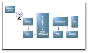
Figure 1:Bock Diagram of System Architecture
The AT89C51 controls the relay state via driver and this in turn determines the state of the connected appliance, whether switched on or off. The connected number of appliances depends upon the number of pins of microcontroller assigned as an output. Depending upon the power source, both Direct Current (DC) and Alternating Current (AC) appliances can be connected. Mostly home automation systems include control of HVAC, security and monitoring systems.
3. Android Application Development
The environment for the Android Application Development is Eclipse. The Eclipse Platform is aimed for building Integrated Development Environments (IDEs), and subjective tools. By Eclipse, it is often meant the Eclipse Software Development Kit (SDK) which is both the leading Java™ IDE and the single best tool available for building products based on the Eclipse Platform. An android application has been developed in order to provide a user friendly interface using Eclipse IDE. Android applications are written in the Java programming language. The Android SDK provides tools for code compilation and packaging data and resource files into an archive file with ‘.apk’ extension called as an Android package. Android devices used the ‘.apk’ file to install the application. Android’s application framework allows for the creation of extremely rich feature and novel applications by using a set of reusable components.
The system application is designed to receive an IP address and a port number of the server, to which control circuitry has been connected. An application is capable of communication between the mobile device and the server.
3.1. Manifest file
The Android manifest file is the central configuration file for an Android application. The editor organizes the manifest information into a number of tabs like Manifest, Application, Permissions, Instrumentation and AndroidManifest.xml.
The tabs that are concerned regarding the application are Permissions and AndroidManifest.xml. In Permissions tab, two permissions for the application are used as the system requires internet connection to send instructions to server on the other end. i.e.
- permission.INTERNET
- permission.NETWORK
AndroidManifest.xml launches different class activities according to their intents. One of these is a launcher activity which in this case is .Pic. When this activity executes, it passes the intent of next activity to manifest file and Android manifest launches the next activity which is .MainActivity.
3.2. Java classes
The application has three Java classes
- java
- Java
- Java
First class refers to a package followed by imports required for application and the later class defines its functions.
3.3. XML file
There are two xml files in the application of which, one is pic.xml that is called by Pic.Java and other is activity_main.xml called by MainActivity.Java. These xml files give the graphical layout or in other words the interface of activity. They have different attributes in them like buttons, toggle buttons, scrolls, texts, editable texts, layouts, check boxes etc. This has been used in the application as a splash screen that stays for 3 seconds when the application has been opened. The graphics are as given in Figure 2.

Figure 2: Splash Screen
The activity_main file includes editable text, text views and toggle buttons in it. Each button and text has its own id so that it can be accessed in future. In the application, editable text1 is for IP address of the device in which server code is running while editable text3 is for port which is always 4444. Each button is for switching of an appliance like fan, light, door, modem etc.
An on-click listener actually sends a defined data after every button has been toggled. The data that is specified with each button is listed in Table 1. Buttons are ambalished with appropriate pictures which are placed in drawable folder as given in Figure 3.
| Toggle button | Port | Data sent to port |
| Fan on | 4444 | 1 |
| Fan off | 4444 | 2 |
| Light on | 4444 | 3 |
| Light off | 4444 | 4 |
| Door open | 4444 | 5 |
| Door close | 4444 | 6 |
| Alarm on | 4444 | 7 |
| Alarm off | 4444 | 8 |
Table 1: Data sent by application to the port
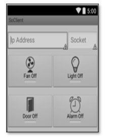
Figure 3: Application Layout
Finally when the code has been debugged, eclipse make an apk file of the application which is to be installed on an android device on which it is supposed to run. It can also be licensed by Google and uploaded on Google playstore but this application being very specific in design is to be provided as a complete package along with hardware control chip.
4. Server
The server is a Dynamic Link Library (dll) that is providing an interface between the Wi-Fi and the serial port. The link is developed and hence the messages received from phone are transmitted to serial port where microcontroller has been attached. Its works by running its batch file as shown in Figure 4 .
The COM5 port has been addressed as 4444 that is receiving data and according to the Table, the server has successfully received the sent data. This data is further to be sent to serial port where the microcontroller will be able to get this serially on its receiving port.
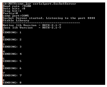
Figure 4: Server Operation
5. Hardware Implementation
5.1. Keil µvision IDE
The program code has been written in Keil and debugged here for any errors. The code is built into a target and the hex file is saved that can be imported to Proteus for simulating the circuit. The algorithm of the program is given by the flowchart of the program as given in Figure 5.
The code includes all <reg51.h> library that contains all the necessary information about 8051 microcontroller family.
5.2. Proteus
Proteus has been used for testing the system in a virtual environment. The software includes all the components in its built in library that are being used. The connections are established and hex file from Keil is loaded in the microcontroller. A seven segment display and LEDs are used to test the output. Hence, when any button from the application is pressed, the server receives the data and transmits to the virtual serial port that is further connected to microcontroller. The LEDs operate in accordance to the program that has been load. The simulation results can be shown as in Figure 6. The virtual serial port is sending commands that are further read by programmed microcontroller. And hence the LEDs acting as loads are switched ON or OFF. The relay is providing 220V supply for the operation.
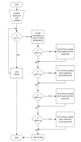
Figure 5: Flow Chart of Microcontroller Program
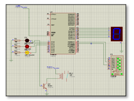
Figure 6: Simulation in Proteus
Diptrace has been used for the Printed Circuit Board (PCB) designing of the circuit needed to do the job. The layout is designed here and printed on the butter paper. It is then imprinted over PCB sheet and afterwards etching is done. The PCB layout at DipTrace is shown below in Figure 7. The complete circuit built on a PCB sheet has been mentioned in the following Figure 8.
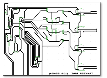
Figure 7: PCB Layout in DipTrace
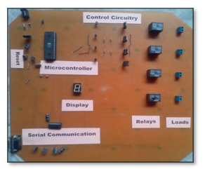
Figure 8: Hardware Circuit
5.3. mikroC PRO for 8051
mikroC PRO for 8051 is a full-featured compiler for 8051 devices. It is the best solution for developing code for 8051 devices. It features intuitive IDE, powerful compiler with advanced optimizations, lots of hardware and software libraries, and additional tools that facilitate the work. Libraries are fully-documented and allow a quick start in programming microcontrollers.
mikroC PRO facilitates to communicate with the COMM ports. Data through serial port is sent to a specific COMM port that has been mentioned below in Figure 9.
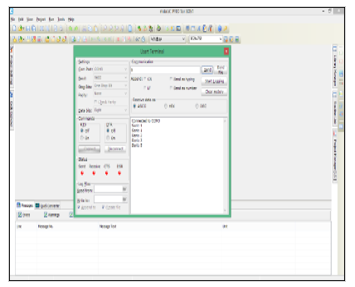
Figure 9: mikroC PRO Programming
5.4. Genius Programmer 540
The GENIUS programmer has its own driver that has to be installed. Afterwards the programmer is connected to computer and a window appears as shown in Figure 10 and the specific microcontroller is selected and the hex file of the code from KEIL is loaded into the controller and hence the burning is done.
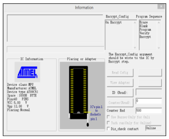
Figure 10: Genius Programmer Operation
6. Results
The designed home automation system was tried and tested several times and verified to control different home appliances used in the lighting system, air conditioning system, heating system, home entertainment system and many more. This follows the condition that the maximum power and current rating of the appliance should not exceed that of the used relay.
Figure 11 shows the installed system in ready state. An android device is ready to send the commands. The server has been installed in a PC having a Wi-Fi connection and the hardware circuit has been attached through a serial port.
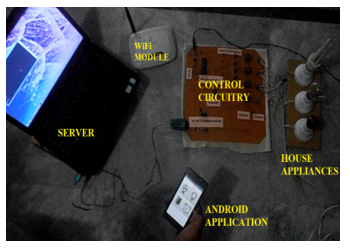
Figure 11: Complete System in Operation
For testing, three bulbs are being used as home appliances. First of all an IP address of the server is to be configured. The IP address is entered into an application. The socket number is fixed that is 4444. As soon as the button has been pressed from the device, the data has been received by PC server and sent to circuit where microcontroller is governing which bulb to be turned on. The turning on of a bulb is shown in Figure 12. For implementation, the bulbs can be replaced by any of the appliance working on 220V. The system was also successfully tested in a room for its fans, lights and air conditioner.
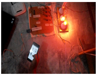
Figure 12: Complete System in Working
7. Conclusions and Recommendation
It is evident from this work that an individual control home automation system can be cheaply made from low-cost easily available components and can be used to control various home appliances ranging from the security lamps, the television to the air conditioning system and even the entire house lighting system. Even better, the parts required are so little and few that they can be bundled into a little slight container.
Finally, this home automation system can be also implemented over Bluetooth, Infrared and WAP connectivity without much change to the design and yet still be able to control a variety of home appliances. Hence, this system is scalable and flexible.
It is recommended to use a serial Wi-Fi module as a server for ease and where cost is not an issue. Further it would be recommended for the followers to achieve such a system that would also be able to monitor the devices in addition to their control. This can easy be implemented by the usage of TX pin of the microcontroller.
Conflict of Interest
The authors declare no conflict of interest.
Acknowledgment
The authors wish to thank University of Engineering and Technology, Lahore, Pakistan for providing an excellent platform for the work.
- Reinisch, C. Kastner, W. Neugschwandtner, G. Granzer, “Wireless Technologies in Home and Building Automation,” Industrial Informatics, 2007 5th IEEE International Conference on , vol. no 1., pp.93-98, 23-27 June 2007
- Jinsoo Han; Chang-Sic Choi; Ilwoo Lee, “More efficient home energy management system based on ZigBee communication and infrared remote controls,” Consumer Electronics, IEEE Transactions on , vol.57, no.1, pp.85,89, February 2011.
- Erdem, H.; Uner, A., “A multi-channel remote controller for home and office appliances,” Consumer Electronics, IEEE Transactions on , vol.55, no.4, pp.2184,2189, November 2009.
- P. Chaudhari and M. K. Chopade, “Ethernet based field control module for industrial process monitor and control using ATmega328,”2016 International Conference on Communication and Signal Processing (ICCSP), Melmaruvathur, 2016, pp. 2098-2101.
- Moravcevic, M. Tucic, R. Pavlovic and A. Majdak, “An approach for uniform representation and control of ZigBee devices in home automation software,” 2015 IEEE 5th International Conference on Consumer Electronics – Berlin (ICCE-Berlin), Berlin, 2015, pp. 237-239.
- Puri and A. Nayyar, “Real time smart home automation based on PIC microcontroller, Bluetooth and Android technology,”2016 3rd International Conference on Computing for Sustainable Global Development (INDIACom), New Delhi, 2016, pp. 1478-1484.
- Lee, Minseok, Younggi Kim, and Younghee Lee. “A home cloud-based home network auto-configuration using SDN.” Networking, Sensing and Control (ICNSC), 2015 IEEE 12th International Conference on. IEEE, 2015.
- Bian, Jiali, Dengke Fan, and Junming Zhang. “The new intelligent home control system based on the dynamic and intelligent gateway.” Broadband Network and Multimedia Technology (IC-BNMT), 2011 4th IEEE International Conference on. IEEE, 2011.
- Hua, Liu Yan, and Zhang Ji Xiang. “Smart home based on the Zigbee wireless.” Intelligent Networks and Intelligent Systems (ICINIS), 2012 Fifth International Conference on. IEEE, 2012.
- Mingfu and L. H. Ju , “ Design and Implementation of Smart Home Control System Based on Wireless Sensor Networks and Power Line Communications ”, IEEE Trans. Ind. Electron. , vol. 62 , no. 7 , pp. 4430 – 4442 , July 2015 .
- Zanella , N. Bui , A. Castellani , L. Vangelista , and M. Zorzi , “ Internet of Things for Smart Cities ”, IEEE Internet of Things Jou. , vol. 1 , no. 1 , pp. 22 – 32 , Feb. 2014 .
- Domínguez, A. Touhafi, J. Tiete and K. Steenhaut, “Coexistence with WiFi for a Home Automation ZigBee product,”2012 19th IEEE Symposium on Communications and Vehicular Technology in the Benelux (SCVT), Eindhoven, 2012, pp. 1-6.