Detailed Analysis of Torque Ripple in High Frequency Signal Injection based Sensor less PMSM Drives
Detailed Analysis of Torque Ripple in High Frequency Signal Injection based Sensor less PMSM Drives
Volume 2, Issue 1, Page No 206-213, 2017
Author’s Name: Ravikumar Setty A.a), Kishore Chatterjee
View Affiliations
Electrical Engineering Department, IIT Bombay, Mumbai-400076, India
a)Author to whom correspondence should be addressed. E-mail: ravikumar.setty@honeywell.com
Adv. Sci. Technol. Eng. Syst. J. 2(1), 206-213 (2017); ![]() DOI: 10.25046/aj020125
DOI: 10.25046/aj020125
Keywords: Sensor less control, High frequency signal injection, Torque Ripple, Audible Noise, Permanent Magnet Synchronous Motor.

Export Citations
High Frequency Signal Injection based techniques are robust and well proven to estimate the rotor position from stand still to low speed. However, Injected high frequency signal introduces, high frequency harmonics in the motor phase currents and results in significant Output Torque ripple. There is no detailed analysis exist in the literature, to study the effect of injected signal frequency on Torque ripple. Objective of this work is to study the Torque Ripple resulting from High Frequency signal injection in PMSM motor drives. Detailed MATLAB/Simulink simulations are carried to quantify the Torque ripple at different Signal frequencies.
Received: 23 December 2016, Accepted: 20 January 2017, Published Online: 28 January 2017
1. Introduction
Permanent Magnet Synchronous Motors are driven with Vector control drives to improve the dynamic performance of the drive. Vector control requires rotor position to control the drive. Position sensor like resolver or encoder are used to provide the rotor position information [1], such a position sensor reduces the reliability of the system and increase the cost and weight of the drive. Sensor less control techniques are widely used to address the position sensor issues [2]. Sensor less control techniques uses only terminal variables (voltages and currents) to determine the rotor position. Back EMF (Electro Motive Force) based methods are popular and robust to extract rotor position information from medium to high speeds. These techniques require minimum motor speed for proper drive operation, however all the techniques based on back EMF, have serious problem to extract the rotor position from low speed to standstill [3]-[4]. At standstill, motor back EMF is zero, so all Fundamental methods based on back EMF fail to extract rotor position information.
According to the type of injected signal, continuous signal injection consists of a rotating sinusoidal signal injection [8] -[10], a pulsating sinusoidal [11] -[12], a square wave signal injection [13] , or arbitrary injection [14].From low speed to standstill machine geometrical or saturation saliency is used to estimate rotor position information. The idea behind saliency based sensor less estimation scheme is that, as the machine winding inductance is function of the rotor position due to saliency, the rotor position is derived from the profile of inductance variation. Position estimation based on machine magnetic saliency or signal injection techniques are powerful from standstill to minimum speed. In order to reveal the position information from machine saliency property, high frequency voltage signal is injected and resulting response current is demodulated to extract position information [5]-[7].
– Continuous signal injection
– Transient signal injection
– PWM excitation without additional injection
The implementation of HF injection schemes is well proven and can be made with standard low cost micro controllers. The response to the injected high frequency signal is used to extract non-zero-sequence current [15], non-zero sequence current derivative [16], which provide the rotor position information. Methods injecting a rotating or pulsating carrier, require filtering in order to distinguish the carrier current response from the fundamental current. This introduces considerable amount of delay, which degrades the dynamics of the sensor less control. This problem is addressed in [17], but their proposals require more complex signal processing and are parameter dependent. Other disadvantage with this method is significant current distortions and torque ripple.
Apart from signal injection techniques open-loop startup methods [18] also used, but these methods are not reliable when enough starting torque motor needs. At start up motor can rotate in reverse direction from the desired direction until the rotor aligned to the known pre-defined position.
In transient injection methods the fundamental current is not affected by high frequency component, but phase currents have significant spikes during the test vector instances. Main concern with the transient signal injection method is the minimum acquisition time for the measurement. The current disturbances also cause additional losses and in some cases undesired torque ripple [19]-[20]. The worst problem is however a significant audible noise, which cannot be neglected for many applications.
To overcome this problem, the inherent excitation of the PWM is used in [21]-[23]. Again, a complex signal processing is required. Implementation of the transient voltage methods requires a more complex and advanced micro controller system. Sensor less control techniques in the low speed to stand still region utilizes the magnetic saliency of the machine to extract rotor position information, however the injected signal could be continuous or transient.
Transient signal injection technique requires current sensing with high bandwidth and which makes current sensing system expensive. This limits the popularity of the transient signal injection techniques. On the other hand continuous signal injection techniques doesn’t need expensive current sensing system , but the injected amplitude causes torque ripple, audible noise and HF losses[24]-[25] .
This work focus on detailed analysis of torque ripple resulting from rotating high frequency signal injection based sensor less control.
2. Modelling of PMSM in d-q reference frame for Torque Ripple Analysis
Detailed modeling of PM motor drive system is required for proper simulation of the system. The d-q model has been developed on rotor reference frame. There are many variations of rotor configurations are reported in the literature. Two main configurations of PM synchronous motors are surface magnet type where magnets are mounted on the outer surface of the rotor (SPMSM), and the interior magnet type where the magnets are mounted inside the magnetic structure of the rotor (IPMSM). Surface and interior type rotor configurations are shown in Fig.1.
Mounting the magnets to the surface of the rotor is the simplest and cheapest method for construction of PMBL motor. Another method for mounting the magnet is to imbed them in the interior of the rotor. Interior design provides mechanical robustness and smaller air gap, which results in a component of reluctance torque in addition to the developed torque due to PM excitation. This work analyze the torque ripple on IPM type motor based on high frequency signal injection technique.
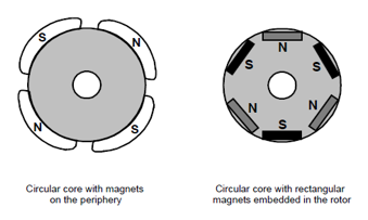
Fig.1. Surface and interior type rotor configurations.
Symmetrical three phase PMSM on stator side is represented with Equations (1) to (3).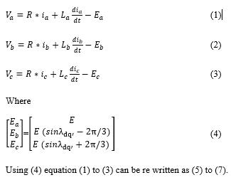
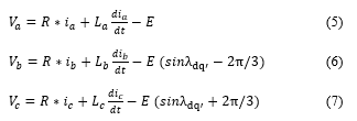
Fig. 2 (a) shows the cross section of a three phase PMS motor showing three phase stator windings A, B and C. The shaded areas of the motor section symbolize areas with a high permeability. It can be seen that the relative air gap width changes with the rotor position dq’. The change of the relative air gap changes the values of the resulting three phase equivalent inductances , and as shown in Fig. 2 (b).
Stator winding inductance has two components one is fixed and second one changes with the position of the rotor. First component is the combination of self and mutual inductance, this doesn’t include the saliency of the machine and second component depends on the saliency of the machine and rotor position. The three phase equivalent inductances , and are given by (9) to (11), which consist of a constant term L plus a Sinusoidal modulation depending on ΔL and the rotor position . It is assumed that saliency causes a balanced sinusoidal three phase inductance modulation.
Fig.2. Three phase equivalent inductance modulation because of saliency
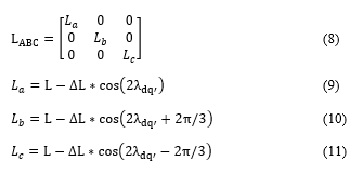
Transforming the inductance vector from stationary reference frame to rotating reference frame dq’ frame gives (13), which shows that the complete saliency of the machine can be described by two variables Ld’ and Lq’ , which define the equivalent inductance values into d’ and q’ axis.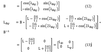
The stator fixed -reference frame model transformed into a rotor fixed reference frame by using the Park-transformed inductance matrix. PMSM model in rotor reference frame can be expressed as shown in (14) to (15).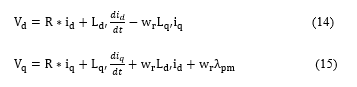
Based on (14) and (15) PMSM d-q model can be represented as shown in Fig.3.
Electromagnetic torque ( with stator variables in the rotor reference frame can be expressed as
3. Position Estimation using High Frequency Signal Injection Technique
This section briefly describe the Vector Controlled Drive operation and position estimation using High Frequency Signal Injection Technique.
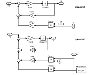
Fig.3. PMSM Electrical model in dq reference frame.
3.1. Vector Controlled PMSM Drive using Position Sensor
Fig.5. depicts the basic block diagram of Vector control of PMS motor drive. Motor phase currents are sensed and then a two phase to three phase transformation is carried out with Clarke transform and Park transform. The motor phase currents ia and ib are measured with a current sensor. The Clarke transform is applied to the measured currents to determine the stator current projection in a two coordinate non-rotating frame. The Park co-ordinate transformation is then applied in order to obtain its projection in the (dq) rotating frame.
In order to control the mechanical speed of the motor, an outer speed loop driving the reference current Iq_ref is provided. The actual speed is compared with the reference speed and the error is processed with a speed controller. The output of the speed controller provides the reference value of the quadrature axis current for the inner quadrature current loop. The inner quadrature current loop process the quadrature current error through a current controller to provide the reference value of the quadrature axis voltage.
For operation in constant torque region the reference value of id is held at zero. The direct axis current is compared with its reference value and the resulting error is processed through the current controller to provide the reference value of the direct axis voltage. The reference direct axis and quadrature axis voltages are fed to the inverse Park transform block to carry out transformation from dq frame to αβ -frame. Thus, the outputs of the current controllers are passed through the inverse Park transform and a new stator voltage vector is impressed to the motor using the Space Vector Modulation technique.
3.2. Sensor less Vector Controlled PMSM Drive using High Frequency Signal Injection Technique
A constant amplitude voltage vector rotating at high frequency (500 to 1500 Hz) is superimposed on the fundamental voltage vector. Therefore a rotating HF current vector arises and which is superimposed on the fundamental current vector. High frequency carrier current response is extracted by a band pass filter from the measured machine currents and filter carrier current is demodulated to reconstruct the rotor position. Negative sequence carrier current contains rotor position information, but all these signals are hidden in the much stronger fundamental stator current and the switching frequency harmonics. Heterodyning demodulation method is popularly used to extract the rotor position signals from the measured stator currents. This work uses heterodyne technique [2] to extract the Rotor Position.
4. Torque Ripple Due to High Frequency Signal Injection
This work deals with the torque ripple analysis of rotating signal injection in αβ -reference frame whose block diagram is shown in Fig.6. A high frequency signal is superimposed to the fundamental voltage vector. The resulting current vector ic will follow the injected rotating voltage vector with 90 °phase shift. However, the locus of the resulting high frequency carrier current response will not be exactly circular due to the stator inductance difference between d-axis and q-axis. Heterodyne demodulation method shown in Fig.7 is used in this work to derive the rotor position from carrier current response.
High frequency signal is injected to extract the rotor position information; but injected high frequency signal introduces torque ripple. This section derives analytical expressions for the torque ripple due to high frequency signal injection. Phase currents will have two components i.e fundamental component and high frequency component resulted from high frequency voltage injection and these current can be expressed as shown in (21) to (23)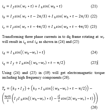
First term in (26) is constant torque component and remaining terms contributes to torque ripple.
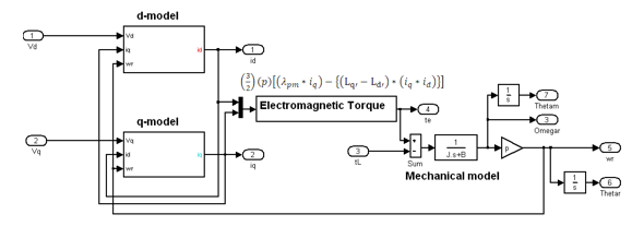
Fig.4. Complete PMSM model in dq reference frame.
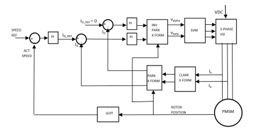
Fig.5. Block diagram of Vector Controlled PMSM Drive
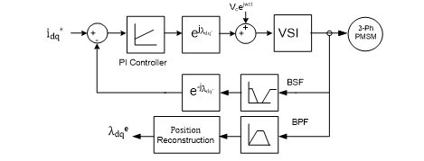
Fig.6. Block diagram of rotating HF voltage carrier injection based Sensor less Drive
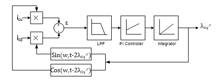
Fig.7.Hetero dyne observer using PI Controller to track rotor position
5. Simulation Results
First sensor less vector control system based on rotating high frequency signal injection is simulated using MATLAB/Simulink TM. , and same platform is used to study the torque ripple at different injection frequencies. Motor parameters used in the simulation are: Ld=16mH, Lq=20mH, 4 poles on rotor and VDC =100V.
Fig.8 shows the phase currents, alpha beta currents, dq currents and output torque at 20Hz speed without signal injection, based on the technique presented in Fig.5. Torque ripple frequency is the difference of injected frequency and fundamental frequency and amplitude fairly direct proportional injection amplitude. Two fundamental currents are considered to compare the, effect of torque ripple at fixed signal injection frequency. Fig.9 and Fig.10 compare the torque ripple frequency at 20Hz and 200Hz fundamental frequency with injection frequency set to 1000Hz. From Fig.9 and Fig.10 it is clear that when the fundamental frequency comes in the order of injection frequency, phase currents distortion is much higher. Higher torque ripple increase the acoustic noise and vibration, so signal injection techniques should be used only for the low speeds.
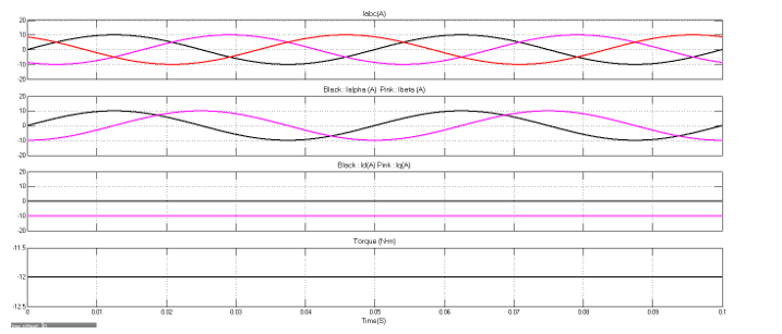
Fig.8. Phase currents, alpha beta currents, dq currents and output torque without any injected signal, stator current frequency = 20Hz
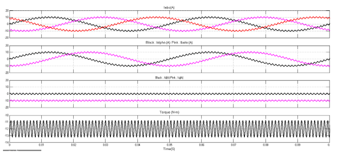
Fig.9. Phase currents, alpha beta currents, dq currents and output torque with injected signal, stator current frequency = 20Hz, Signal Injection frequency = 1000Hz, Signal amplitude = 0.1*Ipeak
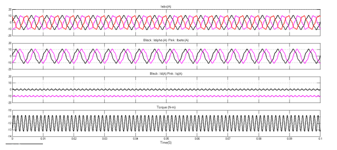
Fig.10. Phase currents, alpha beta currents, dq currents and output torque with injected signal, stator current frequency = 200Hz, Signal Injection frequency = 1000Hz, Signal amplitude = 0.1*Ipeak.
6. Conclusions
This work developed a detailed analysis on Torque Ripple of IPMSM drive based on rotating high frequency signal injection techniques. It is shown that Torque component contains a constant term and high frequency ripple. When the fundamental frequency comes close to the injection frequency, phase currents distortion is much higher and torque ripple also impact the drive operation. This analysis concludes high frequency signal injection method at high speed results in torque ripple and motor vibrations.
Conflict of Interest
The authors declare no conflict of interest.
- Vas, Vector Control of AC Machines. Oxford: Oxford University Press,1990.
- O. Benjak, D. Gerling, “Review of Position Estimation Methods for IPMSM Drives without a Position Sensor Part II: Adaptive Methods”, in Conf. Rec., IEEE-ICEM, September 2010, pp. 1-6.
- T. Kim, H. Lee, and M. Ehsani, “State of the Art and Future Trends in Position Sensorless Brushless DC Motor/Generator Drives”, Proc. of the 31th Annual Conference of the IEEE-IECON, November 2005, pp. 1718-1725.
- T. Kim, H. W. Lee, and M. Ehsani, “Position sensorless brushless DC motor/generator drives: Review and future trends,” IET Elect. Power Appl., vol. 1, no. 4, pp. 557–564, Jul. 2007.
- D. Raca, P. Garcia, D. D. Reigosa, F. Briz, and R. D. Lorenz, “Carriersignal selection for sensorless control of PM synchronous machines at zero and very low speeds,” IEEE Trans. Ind. Appl., vol. 46, no. 1, pp. 167–178, Jan./Feb. 2010.
- José Carlos Gamazo-Real , Ernesto Vázquez-Sánchez and Jaime Gómez-Gil “ Position and Speed Control of Brushless DC Motors Using Sensorless Techniques and Application Trends” Journal of sensors , 2010, 10, 6901-6947.
- Roberto Leidhold, “Position Sensorless Control of PM Synchronous Motors Based on Zero-Sequence Carrier Injection” IEEE Transactions on Industrial Electronics, vol. 58, no. 12, December 2011
- N. Matsui, “Sensorless PM brushless DC motor drives,” IEEE Trans.Industrial Electronics, vol. 43, no. 2, pp. 300-308, 1996.
- Hyunbae, K., Kum-Kang, H., Lorenz, R.D., Jahns, T.M.: ‘A novel method for initial rotor position estimation for IPM synchronous machine drives’, IEEE Trans. Ind. Appl., 2004, 40, (5), pp. 1369–1378
- Yu-seok, J., Lorenz, R.D., Jahns, T.M., Seung-Ki, S.: ‘Initial rotor position estimation of an interior permanent-magnet synchronous machine using carrier-frequency injection methods’, IEEE Trans. Ind. Appl., 2005, 41, (1), pp. 38–45
- Yi Li, Z. Q. Zhu, Fellow, IEEE, David Howe, Chris M. Bingham, Member, IEEE, and Dave A. Stone “Improved Rotor-Position Estimation by Signal Injection in Brushless AC Motors, Accounting for Cross-Coupling Magnetic Saturation”, IEEE Trans. Ind. Appl, VOL. 45, NO. 5, SEPTEMBER/OCTOBER 2009 1843.
- S. Murakami, T. Shiota, M. Ohto, K. Ide, and M. Hisatsune, “Encoderless servo drive with adequately designed IPMSM for pulse-voltageinjection-based position detection,” IEEE Trans. Ind. Appl., vol. 48, no. 6, pp. 1922–1930, Nov./Dec. 2012
- Sung Park, S. Hun Lee, C. Moon, and Y. Ahn Kwon, “State Observer with Stator Resistance and Back-EMF Constant Estimation for Sensorless PMBL MOTOR”, IEEE Region 10 Conference, TENCON 2010, November 2010, pp. 31-36.
- F. De Belie, P. Sergeant, and J. A. Melkebeek, “A Sensorless Drive by Applying Test Pulses Without Affecting the Average-Current Samples”, IEEE Transactions on Power Electronics, Vol. 25, No. 4, April 2010, pp. 875-888
- S. Bolognani, S. Calligaro, R. Petrella, and M. Tursini,”Senseorless Cotnrol of IPM Motors in the Low-Speed Range and at Standstill by HF Injection and DFT Processing”, IEEE Trans. Ind. Appl. vol. 47, no. 1, pp. 96-104, Jan./Feb. 2011
- E. Robeischl and M. Schroedl, “Optimized INFORM measurement sequence for sensorless PM synchronous motor drives with respect to minimum current distortion,” IEEE Trans. Ind. Appl., vol. 40, no. 2, pp. 591–598, 2004.
- Toliyat, HA, Hao, L, Shet, DS, and Nondahl, TA “Position-sensorless control of surfacemount permanent-magnet AC (PMAC) motors at low speeds”, IEEE Transactions Industrial Electronics,2002, IE-49, No 1, pp 157-164
- Ravikumar Setty .A ,Shashank Wekhande and Kishore Chatterjee “Comparison of high frequency signal injection techniques for rotor position estimation at low speed to standstill of PMSM” IICPE 2012.
- Y. Hua, “Sensorless control of surface mounted permanent magnet machine using fundamental PWM excitaiton”, PhD Thesis, Department of Electrical and Electronic Engineering, University of Nottingham, 2009.
- Y.S. Jeong, R.D. Lorenz, T.M. Jahns, and S.K. Sul, “Initial rotor position estimation of an interior permanent-magnet synchronous machine using carrier-frequency injection methods,” IEEE Trans. Industry Applications, vol. 41, no. 1, pp. 38–45, 2005.
- Ravikumar Setty, A.; Wekhande, Shashank and Chatterjee, Kishore “Adaptive signal amplitude for high frequency signal injection based sensor less PMSM drives” IEEE International Symposium on Sensorless Control for Electrical Drives and Predictive Control of Electrical Drives and Power Electronics (SLED/PRECEDE) Munich, Germany ,17-19 Oct. 2013.
- Zhu, Z.Q., Gong, L.M.: ‘Investigation of effectiveness of sensorless operation in carrier-signal-injection-based sensorless-control methods’, IEEE Trans. Ind. Electron., 2011, 58, (8), pp. 3431–3439
- J. Holtz, “Acquisition of position error and magnet polarity for sensorless control of PM synchronous machines,” IEEE Trans. Industry Applications,vol. 44, no. 4, pp. 1172–1180, 2008.
- Ravikumar Setty, A. ; Wekhande, Shashank and Chatterjee, Kishore “Compensation of rotor position estimation error due to stator winding resistance in signal injection based sensor less PMSM drives” IEEE International Symposium on Sensorless Control for Electrical Drives and Predictive Control of Electrical Drives and Power Electronics (SLED/PRECEDE) Munich, Germany ,17-19 Oct. 2013.
- Yan, Y., Zhu, J.G., Guo, Y.G.: ‘Initial rotor position estimation and sensorless direct torque control of surface-mounted permanent magnet synchronous motors considering saturation saliency’, IET Electr.Power Appl., 2008, 2, (1), pp. 42–48.