Development of a Motorized Afifia Mowing Machine Design for Controlling Environmental Conservation and Menace for Home Use
Development of a Motorized Afifia Mowing Machine Design for Controlling Environmental Conservation and Menace for Home Use
Volume 2, Issue 1, Page No 177-185, 2017
Author’s Name: Gbasouzor Austin Ikechukwua), Mbunwe Josephine Muncho2
View Affiliations
1Department of Mechanical Engineering, Chukwuemeka Odumegwu Ojukwu University, Formerly Anambra State University, P. M. B. 02 Uli. Nigeria.
2Department of Electrical Engineering, University of Nigeria Nsukka Nigeria.
a)Author to whom correspondence should be addressed. E-mail: unconditionaldivineventure@yahoo.com
Adv. Sci. Technol. Eng. Syst. J. 2(1), 177-185 (2017); ![]() DOI: 10.25046/aj020121
DOI: 10.25046/aj020121
Keywords: Convenience, Conventional manual method, Environmental Conservation, Lawn Grass, Mowing, Reel, Rotary Cutters, Rotating Blades

Export Citations
Technology has become more affordable and penetrates every aspect of daily life, even in developing country like Nigeria. However many of the users in developing countries are still finding difficulty in using the technologies due to lack of experience as they undergo a technology leap. The aim of this research work explores the approach in designing, development of a motorized Afifia (grass) mowing machine. This research was considered because of the unhygienic environmental conservation and its menace. An estimate of 20N was adopted as the required force to cut lawns and based on this design force of 70N was chosen. This design force was the basis of characterizing the selection of materials use, as a result it was found that the machine is 85% efficient based on the area mowed per hour which is 390.6m2.
Received: 21 December 2016, Accepted: 18 January 2017, Published Online: 28 January 2017
1. Introduction
A mower is a person or machine that cuts (mows) grass or other plants that grow on the ground. We may want to keep a cleaning environment around our houses. Then we need to remove unnecessary grass on the compound and also if somebody need to make a new sport ground or maintain a current ports ground, we need to put a certain grass level. To do that, we use a very tool which known as lawn mower. Thus a lawn mower is a machine that uses a revolving blade or blades to cut a lawn at an even length. Actually there are plenty of various types of lawn mowers, but we need to choose the best one according to our work. There are 3 types of lawn mowers which are,
- Push type: a human needs to push it
- Ride on type: a human rides it
- Multi-gang type: pulled behind a tractor
Firstly, we need to identify which kind of lawn mower needed for our work
- For or home purposes, we need to use push type.
- For sports ground purposes, we need ride on type.
- For even bigger grounds such as golf grounds are multi-gang type.
A smaller mower used for lawns and sports grounds (playing fields) is called a lawn mower or grounds mower, which is often self-powered, or may also be small enough to be pushed by the operator. Grounds mowers have reel or rotary cutters. Larger mowers or mower-conditioners are mainly used to cut grass (or other crops) for hay or silage and often place the cut material into rows,which are referred to as windrows, Swathers (or windrowers) are also used to cut grass (and grain crops). Prior to the invention and adoption of mechanized mowers, (and today in places where use of a mower is impractical or uneconomical), grass and grain crops were cut by hand using scythes or sickles. Lawn mower is simply described as a machine used for cutting or mowing grass. Petrol driven rotary lawn mower is a piece of equipment that provides the convenience of keeping the lawn grass short. It serves as a substitute for the conventional manual method and pushed gasoline lawn mower; which has been found not only inefficient but so labour intensive.
A lawn mower is a machine utilizing one or more revolving blades to cut (afifia/grass) surface to an even height. The height of the cut grass may be fixed by the design of the mower, but generally is adjustable by the operator, typically by a single master lever, or by a lever or nut and bolt on each of the machine’s wheels. The blades may be powered by muscle, with wheels mechanically connected to the cutting lades so that when the mower is pushed forward, the blades spin, or the machine may have a battery-powered or plug-in electric motor. The most common power source for lawn mowers is a small (typically one cylinder) internal combustion engine, particularly for larger, self-propelled mowers. Smaller mowers often lack any form of propulsion, requiring human power to move over a surface; “walk-behind” mowers are self- propelled, requiring a human
only to walk behind and guide them. Larger lawn mowers are usually either self-propelled “walk-behind” types, or more often, are “ride-on” mowers, equipped so the ‘operator can ride on the mower and control it.
1.1. The Application of Lawn Mower
The application of the lawn mower is extensive. The rise of sporting activities like football, cricket and golf has necessitated the use of these machines more extensively.
Moreover, the use of motorized lawn mower has helped in saving time and energy when compared with manual cutting of grasses.
But even with the above advantages of motorized lawn mower, it is still found that manual labour is still largely applied in Nigeria. This may be as a result of the cost of producing a lawn mower. It is therefore our intention to construct and fabricate motorized petrol driven lawn mower at a greatly reduced cost so that the common man can afford it.
1.2. Aims and Objective
This machine was constructed with, the design of a tricycle unlike the convectional four wheel drive. A snuffer was constructed as part of the machine to keep Mown grasses on a straight line along the path of the Lawn mower. This serves to protect the operation from propelled broken pebbles. Also, it is our inspiration to design and construct a functional motorized tricycle gasoline powered Lawn mower at a reduced cost, compared to the conventional four wheel driven, in the market.
- This method is injurious, laborious, and unhygienic and produces non-uniform cutting and thereby giving poor end finishing.
- It uses human energy, slow and labour intensive
- The design and development of motorized afifia mowing machine will provide a relief of human labour speed up cutting and produces uniform cutting or clearing for a better end finishing
1.3. Scope of Research
The design and fabrication is considered with the constraints and consideration discussed. The study aim to produce a cost effective lawn mower that is driven by a petrol engine with the capability to mow lawns to an optimal height of 20mm (2cm) Using simple belt and chain drive mechanism in order to ease operation and maintenance of the machine.
2. Enviromental Importance of Fefea/Grass Moving Machine
Grass cutting is a tedious work for man became it requires a lot of energy especially using local hand-tools. This difficulty led to the development of devices that could ease the cutting process (Drake and Hermick, 1983). Some of these devices include the Reel mower, electric trimmer and the Hand sheare. Although these’ devices still depended on the use of hands, it was relatively easier than using cutlasses. In the process of developing these simple devices, the LAWN MOWER was invented (Greamer, 1964). The first Lawn mower was invented in 1830 by EDWIN BREAD BUDDING, an engineer from Stroud, Gloucester- shire, England. He developed the idea from observing a machine in a local cloth mill which used a cutting cylinder (or blade reel) mounted on a bench to trim cloth to make a smooth finish. After weaving, Budding realized that a similar concept could be used in cutting grass if the mechanism could be mounted on a wheeled frame to make the blade rotate close to the Lawn’s surface. He then collaborated with a local Engineer, John Ferrabee and together they developed the idea and produced the first Lawn mower in a factory at Stroud. The machine was made of art iron with geared wheels transmitting power from the rear roller to the cutting cylinder. Budding and Ferrabee were shrewd enough to allow other companies build copies of their mower under license. The most successful of these was Ransom’s of Ipswich which began producing mowers as early as 1932.
The company has continued making Lawn mowers since then and it is now the world’s largest manufacturer of Lawn care equipment (www.kellerstudio.com.4th April, 2008). Other companies apart from Ransoms of Ipswich picked up Budding’s idea. Thomas Green was one of these companies and he produced the first chain driven mower in 1859, named the “Silens Messor” which means the silent cutter. It used a chain to transmit power from the rear roller to the cutting cylinder. These machines were lighter and quietly than the gear driven mowers that preceded them although they were, slightly more expensive. At about the same time, Alexander shanks of Abroath introduced it’s range of Caledonian mower. All were available with either gear or chain drive and Grass collection boxes were optional. Around 1990, one of the best known English machines was the Ransom’s automation which was available in chain or gear driven models. J. P engineering of Leicester, founded after world war one, produced a range of very popular chain driven mowers. About this time an operator could ride behind animals that pulled large machines. These were the first riding mowers (www.wikipedia.com.4th April 2008).
The development of these mowers was aided by the rise in popularity of sports like lawn tennis, football, cricket and rugby, helped prompt spread of these inventions. James Sunner of Lancashire patented the first steam- powered lawn mower in 1893 his machine burn petrol and/or paraffin oil (kerosene) as a fuel.
After numerous advances, the machines were sold by the stilt fertilizer and Insecticide Company of Manchester. The company they controlled was called the Ley Land steam motor company. Numerous manufacturers entered the field with gasoline driven mowers after the turn of the century. The first grass boxes were flat trays but they took their present shape in the 1860’s the roller driven Lawn mower has changed very little since 1930. Gang lawn mowers, those with multiple set of blades were built in the USA in 1919 by a minister, Worthington. His “company was taken over by the Jacob seen corporation but his name is still cast on the frames of the gang units. Rotary mowers were not developed until engines were small and powerful enough to run the blades at a high speed. In 19301 power specialities Itd introduced a gas power rotary mower. However, the machines continue to attract the interest of collectors and enthusiast art throughout the world, which was why the Old Lawn mower club was formed in 1990. (www.reference.com.4th April 2008). EgbeJule Blessing designed an electric Lawn mower at the University of Portharcourt which had the advantages of quick start, less maintenance cost and produced little or no noise Egbejule, 2006). His design however, was limited in use nee it depended on electricity which is never constant in Nigeria. Based on these findings we intend to review Egbejule’s design producing a motorized lawn mower that uses a petrol engine as it’s power
source to eliminate the dependence on electricity. It is our utmost desire to produce this machine at affordable rate.
3. Design of Afifia/Grass Mowing Machine
3.1. Material Selection
For an intelligent and resourceful design, the designer must clearly know the materials, which are available and the properties they posses. Selection of materials depends on factors such as the intensities and types of stresses to which the component is subjected to, whether it is flexible or rigid or it is to experience high temperature or corrosive actions and how it lends itself to processes of manufacture i.e forging, machining e.t.c.
Therefore the designer’s selection will be influenced by the following factors;
- Strength
- Weight
- Appearance
- Manufacture
- Cost of production
These also will determine the variation between success and failure of the machine. We can further classify the above factors into four classes;
- Service requirement
- Fabrication requirement
- Maintenance requirement
- Economic requirement
3.2. Service Requirement
In deciding the choice of a material, the material has to have a certain properties that can fulfill the desired role. These properties called service requirement include strength, stiffness, hardness, corrosion resistance, heat resistance e.t.c.
3.3. Fabrication Requirement
A material must possess some properties that enable it to be worked on. These properties include forgeability, malleability, ductility and ability to be welded. Material undergoing forgeability are heated to a high temperature close to its melting point and then shaped to a desired structure. Malleability entails that the material should be able to take sheet like forms while ductility requires that the material is able to be drawn into the form of a wire. The material must be able to be joined by welding.
3.4. Economic Requirement
This is about the most important factor for the selection of materials because it determines the cost of production, which in turn determines the price of the product and its use by consumers. If the total cost of production is high, consumers will look for cheaper alternatives which will eventually defeat the purpose of the production.
Bearing In mind that the two main aims of production are satisfying human needs and also to make profit, a producer must judiciously select relatively cheaper, but reliable and appropriate materials for production.
This will reduce the overall cost of production. This in turn ensures hat human needs are satisfied and ultimately justifies this project work.
3.5. Maintenance Requirement
This enables the interchangeability of failed parts. Failed parts are expected after the machine has served for some good number of years. But, it does not always go this way if not properly maintained, machine parts can get bad before the expected time or life time. It therefore means that maintenance involves far more than changing parts. It includes day to day activities like clearing, lubricating, tightening of loosed bolts and nuts as all of these have a bearing on the life span “of the product.
3.6. Choice of Material
Based ·on the above considerations, the materials for all parts of the machine were selected. These materials are tabulated in table 3.1 below.
Table 1: Materials selected
| Components | Material | Reasons |
| Chasis | Mild steel | Tough, hard and malleable |
| Blade | Steel | Light weight and resistance to corrosion |
| Bolts and nuts | Mild steel | Tough, hard and malleable |
| Handle | Mild steel | Tough, hard and malleable |
| Shaft | Medium carbon steel | High tensile strength, heat and corrosion resistance |
| Belt | Leather | Tough |

Fig 1: The Designed Afifia Mowing Machine
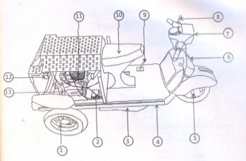
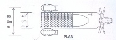
Fig 2: Assembly view of the Afifia mowing Machine
Table 2: Items
| Items | Descriptions | Items | Description |
| 1 | Tire | 7 | Head lamp |
| 2 | Battery | 8 | Clutch lever |
| 3 | Snuffer | 9 | Gear pedal |
| 4 | Chassis | 10 | Seat |
| 5 | Shock Absorber | 11 | Engine |
| 6 | Brake lever | 12 | Rear lamp |
| 13 | Shaft |
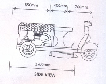
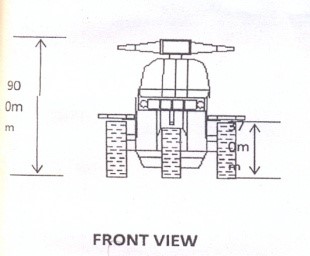
Fig 3: Different Technical Views of the Machine
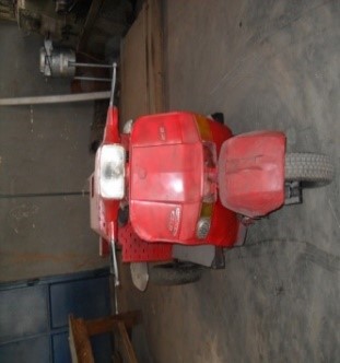
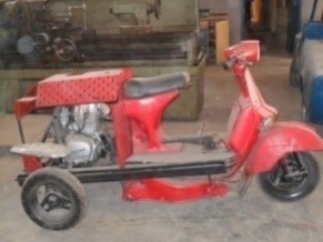
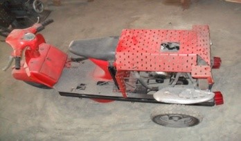
Fig 4: Orthographic Projection of the Machine
3.7. Manufacturing Process of the Chasis
The chasis was constructed from mild steel with thickness 7mm. the sheet was cut with the aid of chisel, hammer, and hacksaw and was developed into the shape of the frame. The mild steel was joined together by metal arc welding. This utilizes heat of the arc between a continuously fed consumable electrode and the work to be welded. The heat of the arc melts the surface of the base metal and the end of the electrode. The metal melted off, the electrode is transferred across the arc to the molten pool. Shielding of the molten pool, the arc and the surrounding area is provided by an envelope of gas fed through a nozzle. The shielding gas surrounds the area to protect it from contamination from the atmosphere.
3.8. Heat treatment of the Blade
The blade was subjected to heat until it became red hot. This is done to distort the grain structures of the metal, after which cooling was controlled in a bow containing oil. This is an attempt to bring the grain structure to a coarse form. This process is known as hardening. The essence of the aforementioned process is to increase the toughness, hardness and strength of the blade, thereby preventing wear to the blade as it makes contact with stones, pebbles, broken bottles etc
3.9. Shaft
The shaft was machined with lathe to a diameter of 70mm and coupled directly to the wheels by means of a lock nut and a key.
3.10. Coupling
The blade was coupled directly to the gear by means of a lock nut and a key.
3.11. Lawn Mower Assembly
Lawn mower components are listed in the table below
Table 3: List of Lawn Component
| S/n | Element | Quantity |
| 1 | 1 C engine | 1 |
| 2 | 1 C engine seating | 1 |
| 3 | Blade | 1 |
| 4 | Front tyres | 1 |
| 5 | Rear tyres | 2 |
| 6 | steering | 1 |
| 7 | operators seat | 1 |
| 8 | Steel chassis | 4 |
The assembling of the component to form the lawn mower is as follows:
An 1C engine positioned at the rear of the chassis is bolted to the chassis. The rear axles with two tyres of 37cm diameter are bolted to the wheels while the blade is directly coupled to the gear in the mower housing. A front tyre of 37cm diameter is also fixed. All tyres are detachable and adjustable to enable changes when bad and to adjust the height of the lawn mower respectively.
3.12. Surface Finish
This process entails remover of spatter formation arising from the intense heat during welding process. This was achieved with the help of grinding disc. Thereafter, energy paper was used to smoothen the affected parts. This process was followed by painting the frame with a black oxide. This was done to prevent corrosion. The machine was then finished by painting the body red.
The design procedure for this study will be discussed under the major heading.
- Problem formulation.
- Design specification.
- Feasibility study.
- Preliminary design
- Detailed design.
3.13. Problem Formulation
There is a, general problem of keeping the environment clean. This often requires keeping lawns at an acceptable height to avoid the problem of harboring snakes and other dangerous animals. A lawn mower will be necessary in achieving this. But, while lawn mower can satisfy this needs, it may not be affordable. A cost effective motorized town mower will therefore be necessary to fully satisfy needs.
A market survey was conducted to ascertain the present cost of a motorized lawn mower of 20.00Hp (14.914kw) engine capacity sells for #400,000; a 15.00 Hp (11.1855kw) engine capacity sells for #300,000. Literature review of past work on this research work was also examined in order to understand the areas that need improvement.
Considering the following constraints:
- Minimum cost
- Limitation of side effect.
- Technological limitation.
- Minimum performance requirement.
3.14. Design Specification
This project is aimed at producing a cost effective one sealer tricycle motorized lawn mower to carry a maximum lead of 80kg.
The motorized lawn mower is going to be mechanically powered with a Qlink 125 engine capacity: – one cylinder, 4 stroke petrol engine
Horse power: .- maximum power, 18hp· (13.1kw)
Max, Output: – 14p.s/ 75000rpm
Max. Torque: – 14N.m /6000rpm
Compression ration: – 9: 5: 1
The design will be typified by the following features;
- A steel chassis for strength and durability.
- Shaft and bearing for the rear wheel.
- Steel metal cutting blade of height 350mm (35cm)
- The handle bar.
- The chain drives transmission for the rear wheel.
- The belt drive transmission for the blade
- Intermediate pulley for tensioning the belt.
- The gear system on the blade.
- The adjuster for the blade.
- The gear lever
- The breaking system.
- The throttle and clutch on the handle
- Position of the seat.
- Force required to move the machine and to cut grass
3.15. Feasibility Study
Different system could be employed in satisfying the design of the motorized lawn mower in order to achieve the aim of this project. A proper feasibility study was carried out from this study. It was observed that different mechanisms can be used to achieve the aim of this work e.g, an electric motor can be used as a source of power. A mechanical system that involves the use of direct gears to transmit the torque from engine to blade and wheels, a robotic system can also be used. From above analysis, we decided to use a petrol engine as the source of power. This was chosen because;
- An electric motor will require the use of long wire during operation. This is inconvenient and may really not appeal to everyone, moreover, in country like Nigeria, where electric power supply is not really available, the use of electric motor will be in appropriate.
- The robotic system is far too expensive to be considered adopting, it defeat the aim of this project.
- The use of direct gear transmission will require a lot of machining; also, it follows with a large noise due to vibrations from the gear.
In the system chosen, the rear axle should be operated on a manual transmission through gears liked with chain and sprocket supported on the shaft of the axle (4 speed, constant mesh gear box).
The blade will be coupled directly to the shaft from the bevel gear box. The bevel gear box will be derived by the engine direct shaft which will be transmitted by belt drive from the engine shaft to the bevel gear box. The cooling system will be forced air cooled. The break will be on internal expending drum consisting of two shoes.
The gears and bearing life will be 712, 00 infinite shaft life. The engine will be located at the rear market. Segment will be of low cost market safety features. Low centre of gravity (C.G) to ensure firm grip of road wheels on the ground cost limitations: < #250,000.
3.16. Preliminary Design of the Chassis
The chassis is an arrangement of angle bars joined together by welding, the chassis is required to carry the engine weight, the mower house, the operations weight and acts as a mounting support for the handle and wheels.
The chassis should be able to keep all the component on. It in there corrects relative positions in spite of all varying stresses which they may be subjected to. As the base on which all other components are attached, it is expected that the weight of the engine, the operators weight, accelerating torques as well as centrifugal forces will all act on the chassis.
3.16.1.Shaft and Bearings for The Rear
An axle shaft is used for transmission of bearing moment. The shaft is coupled with three radial ball bearing which acts as a support to the wheels and also able to withstand the corresponding torque.
3.16.2.Cutting Blade
This is the cutting element of the lawn mower. It is coupled to the bevel gean shaft by a nut and a key for proper fastening. It has a cutting edge on either side along its length. It is made from hardened steel of length 35cm and breath 5cm.
The blade will be acted upon by three forces
(1) Shear force that is impacted’ on the blade as it cuts lawns.
(2) The weight of the blade that tends to drag it out of its attachment paint.
(3) Centrifugal force that tends to pull it out of its path of rotation.
3.16.3.The Handle (Steering)
The steering id through a linkage, with the handle bar directly connected to the front wheel or via a form of Ackerman steering geometry. The handle (steering) carries the throttle control lever, clutch control lever and brake control lever.
The handle will be acted upon by a torque requires to turn the handle by the operator.
3.16.4. Chain-Drive
This is the mechanism that will be introduced in transmitting the output motion of the gear shaft from the engine to the rear wheels (axle).
In designing the chain drive, we ·are to determine the velocity ration of the chain drive, select the minimum number of teeth on the pinion, design power by using the service factor, and choose the type of chain and chain length.
3.16.5.Belt – Drive
The belt drive mechanism will be introduced to transmit the motion from the direct shaft of the engine to the bevel gear box which will drive the blade.
3.16.6. Intermediate Pulley
This will be introduced for constant tensioning of the belt. This is because of different level of the mower housing. The idler pulley will be design in such a way that it will be moving to and fro so that it aims will be achieve.
3.16.7.The Bevel Gear Box
Here, a bevel gear will be used to change the axis of rotational motion of the engine shaft. A miter gears connect two shaft whose axes intersect at right angle. In designing the bevel, we consider the number of teeth of the bevel gear that correspond to the speed required by the blade to mow a particular square size of a lawn at a particular time.
- The Blade Adjuster
Here, a mechanism will be chosen to perform this operation. The arrangement is as shown below
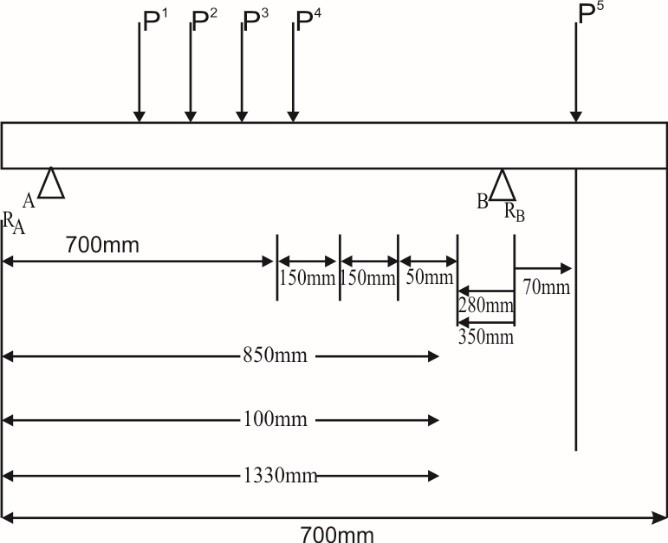
Fig 5: Free body diagram of the chassis frame side member showing the various load distributions.
3.16.8.The Gear Lever
A mechanism will be chosen to serve as gear lever close to the position of the operator. Here, we consider it to be a four bar mechanism as shown below.
3.16.9.The Braking System
The brakes will be an internal expanding drum consisting of two shoes. The effect of this brake is control at the handle of the machine. This is linked by a flexible cord which is operated by pushing the engine brake lever when brake is necessary.
3.16.10.The Throttle and Clutch On The Handle
This is used to control the speed and engagement of gear for operation of the engine. It is formed from a coupling of iron and plastic anchored to the handle. It is linked to the engine by a flexible cord which is operated by pushing the engine throttle when in tension and releases it when free.
3.16.11.Position Of Seat
The position of the seat and height of the seat will be put into consideration for efficient comfort during operation. Here, we shall consider the maximum weight of the operator and expectable height of the operator.
3.16.12.Force Required To Move The Machine And To Mow Grass.
The amount of force needed to mow a lawn is less than 20N. For greater efficiency, a machine that will deliver a Larger force more than that of the cutting force and moving force plus friction will be adopted. Required force = Static friction + Dynamic friction + Cutting force + Maximum force for movement.
4. Fundamental Distributions Analysis of the Machine
Having completed the preliminary design, the various part of the lawn mower will be designed.
4.1. Chassis Frame Design
Considering the side member of the frame, the several load reactions can be distributed and presented as shown below
Where;
P1 = weight of the mower house with blade – 117.72 and gear box
P2= weight of body and frame = 441.5N
P3 = weight of seat 8 operator = 833. 85N
P4 = weight of front engine support = 294.3N
P5=weight of rear engine support = 343.35N
PA = Reaction at support A,
PB= reaction at support B.
4.2. Determination of the Magnitude of the Support Reaction at A and B
For equilibrium of the system,
The resultant moment must be zero
i.e., ∑MA=0
∑MB = 0
The resultant vertical force must be zero
i.e. ∑fy = 0,
Taking moment about B,
i.e. ∑MB=0,
Table 4: Internal stresses
| Section | Shear force |
| A-1 | FA1 F1A= RA= 465.882N |
| 1.2 | F12= F21 = RA= – P1 = 348.162N |
| 2-3 | F23= F32= RA= P1– P2– 93.338N |
| 3-4 | F34= F43= RA-P1– P2– P3 P4=-927.188N |
| 3-B | F4B= FBA= RA– P1– P2= -1221.488N |
| B-5 | FB5= F5B= RA– P1– P2-RB=-2786.328N |
4.3. Design Procedure Of Chain-Drive
The chain drive is design below velocity Ratio of the chain drive,
V.R = T2 N1=1800rpm
T1 N2 = 710 rpm
Where T1 = Number of teeth on the smaller sprocket = 15
T2 = Number of on the large sprocket = 38
:. V.R = T2 = 38 = 2.5333AY 3
T1 15
4.4. Rear Axle Shaft Design
The shaft with a sprocket or gear mounted on the bearings is shown in fig. it is subjected to combined twisting moment and bending moment.
Power, P = 13.1kw= 13,100w, N = 710rpm, D = 0.193m
L =1.2m, Normal load (w) = 1832N
Torque transmitted by the shaft,
T = PX60 = 13100X60= 176.2Nm
2∏N 2∏X710
Tangential force on the gear,
Tt = 2T= 2X176.2 = 1825.91N
D 0.1193
Since the sprocket is mounted at the middle of the shaft, therefore maximum bending moment at the centre of the gear
M = W.L = 1832X1.2 = 549.6Nm
4 4
According to maximum normal stress theory, equivalent bending moment,
Me = 1/2 (M + M2 + T2) = (M + T2)
= 1/2 (549.6 + 577.2) = 563.4Nm
= 563.4 X 10³N mm
Also equivalent bending moment (Me),
563.4 X 103 = X δb X d3 = X17.5Xd3
32 32
d3 = 327928.3015
d = 3√327928.3015 = 68.96mm say 70mm
4.5. Design of Belt-Drive
N1 =7500rpm = N2, d1, = d2 = 100mm = 0.1m
p= 13.1kw, r1 = r2 = 0.05m, µ= 0.3
speed of the belt (v)
v = d1N1 = x 0.1 x 7500 = 39.27m/s
60 60
Power transmitted (p),
13.1 X 103 = (T1-T2) 39.27
.: T1-T2 = 13.1x 10³/39.27 = 333.59N ………….. (i)
We know that
2.3 log (T1/T2) = µ = 0.3 X (.: =1800 rad)
:. Log (T1/T2) = 0.942 = 0.4096
2.3
Or T1/T2 = 2.57 …………………………… (ii)
From equations (i) and (ii),
T1 – T2 = 333.59N and T1/T2 = 2.57
T1 + 2.57 T2
:. 2.57 T2-T2 = 333.59
1.57 T2 = 333.59
T2 = 333.59/1.57 = 2.1.48N
And T1 = 2.57 X 212. 48 = 546N
Let b = Width of the belt in meters
t = thickness of the belt = 10mm
Since the velocity of the belt is more than 10m/s, therefore centrifugal tension must- be taken into consideration. The density of the leather belt used is 1000kg/m3
4.6. Design of Bevel Gear Box
A 90° bevel gearing arrangement is used to drive the mower blade. It is designed thus,
Module and face width for the pinion
Let m = Module in mm
b = face width in mm = L/4
Dp = Pitch circle diameter of pinion
Velocity ration,
V.R. = TG = 44 = 3.667
Tp = 12
:. Speed of the gear,
NG = Np = 7500 = 2045rpm
V.R 3.667
4.7. Pressure on Wheels
The wheel will be acted upon by the three forces.
- The weight of the engine (We)
- The weight of the chassis (Wc)
- The weight of the blade (Wb)
We = 20 x 9.81 = 196.2N
We = density of chassis materials
X volume of chassis (Vc) x 9.81
Vc= Area of chassis x thickness = 1,020m3
= 1.7 x 0.6 x 0.007 = 0.00714m3
= 7.14 x 10⁻³m3
Density of chasis material
= 7861kg/m3
Wc = 7861 x 7.14 x 10-3
= 56.12754 x 9.81
= 550.6N
Total weight on the wheels
= 196.2 + 550.6 + 11.7
= 758.5N
Force acting on the wheels = 758.5
4
= 189.6N
4.8. Determination of the Area Mowed by the Blade During one Revolution of the Wheel
The linear distance covered in one revolution of the wheel, Id
Ld= ITdw = IT x 0.195 = 0.61m
Diameter of the blade, db = 0.35m
Area covered in one revolution Ar
Ar = Ld x db
= 0.61 x 0.35
= 0.21m2
4.9. Determination of Area Mowed in one Hour
Time taken to mow 0.61m
(1 rev of wheel) = 2sec
V= S = 0.61
t 2
= 0.31m/s
Assuming this speed to be constant, the distance covered in one hour (3600s) will be:
S = Vt
= 0.31 x 3600 = 1116m/hr
1116m will be covered in one hour
Area mowed in one hour = distance covered in one hour x diameter of blade
= 1116 x 0.35
=390.6m2
5. Testing and Results
5.1. Test and Results
The machine on complexion was tested on lawn and found working normally with little or no vibration. It was tested on many occasions without giving any sort of problems showing a very satisfactory performance.
The machine was operated for an hour and it was found that the area mowed amounted to 211m. This was as opposed to the expected performance based on calculations.
As a result of the foregoing, we were able to estimate the efficiency based on the performance criteria earlier stated.
Efficiency =
5.2. Discussion
The efficiency of the machine was found to be satisfactory from the results obtained above. This shows that even if the materials were not the best, satisfactory equipment could be produced in other for the machine to work properly; the following procedures must be followed.
5.3. Operational Procedures
The mower uses a dry cell battery to switch on the engine. The starting procedures are as follows:
- Switch on the ignition.
- Press the start button until the engine starts.
- Push the clutch lever and engage the gear.
- Then drive the mower to the area to be mowed ensuring that there are no loose stones, twigs, branches, logs e.t.c.
- Mow along the lawn to give a uniform cut.
- After mowing, disengage the gear and switch off the engine.
5.4. Precautions to be taken
The necessary precautions are as follows:
- Make sure you understand the operation of your mower, especially how to stop it.
- Make sure all protective devices are in place on the mower.
- Wear proper eye protection like plastic eye glasses or safety glasses to protect your eye from flying debris.
- Use earmuff to reduce noise level to the ear.
- Keep curios kids and pets at a safe distance away from the mowing area.
- Mow high sloppy areas from side to side.
- Before operation is made, make sure that there are no stones, debris, bottles, tins, pebbles or any hard object on the grass that could damage the blade.
5.5. Maintenance and Storage
- Before carrying any maintenance or cleaning operation, stop the engine.
- Periodically check the blade to see if it requires re- sharpening or replacement.
- clean and lubricate dry component of necessary
- clean above and below deck to remove dirt, leaves and debris, pay close attention to the blade housing.
5.6. Blade Maintenance
- First jack up the machine and place it on axle stand.
- check to see if the blade is bent
- locate a reference point on one side and known the height of the blade, tip at that location, then rotate the blade and check the height of the opposite blade tip. There should be no significant difference. A difference of say 0.003175m or greater shows that the blade is bent.
- Slight makes and bends can be cleaned up with a file while the blade is still in position. If damage is severe, a replacement will be needed.
5.7. Change of Blade
Changing blade is carried out by a qualified personnel, is carried out as follows,
- Obtain a new blade from the market with the same dimensions as the one in the mower.
- Remove fasteners, i.e bolts and nuts.
- Replace the old blade with the new one.
- Replace fasteners on the new blade
6. Conclusion
A motorized lawn maker which helps to push away obstacles has been built with the list cost possible. The cost of a motorized lawn mower of the same capacity in the market is about N400, 000 while the one produced in this research cost about N250, 000. Comparing the two cost shows that their design achieved its target tremendously. If given the opportunity to produce a mass production of our mower, the cost of production could be as low as N200, 000. It is our belief that our innovation can put more mowers in the hands of consumers and eliminate the dependence of manual labour in our country Nigeria. Finally, it is believed hope that this study will symbolically represent our efforts which are aimed to serve our great country as engineers eliminating problems of the common man.
Recommendation
In our industrialized world, advances in technology are on the increase. It is therefore necessary that we improve on our indigenous technology. While the motorized lawn mower is very useful in eliminating manual labour used in cutting and trimming lawns, the operator is still required to drive the lawn mower during -operation. This too, requires expanding time energy. The advancement in robotics has given rise to robotic lawn mowers. In this type of mower, the operator is not require to push or drive the lawn mower as he cuts the laws. He is just expected to mark out the area and program it on the machine. The machine then moves within the marked areas and cut the lawns on it to the desired height. This machine is quite expensive. It is our recommendation that a research be carried out on this type of lawn mower with a view of producing it on affordable price to consumers who need it.
- Akele S. m. G and sulaimon A.O, (2003) Automotive for beginners Nigeria. Pagasms publishers Auchi page 36.
- Drake C.W and Helmick C. G (1983), industrial motor application, Halsted Inc. New York. Page 62
- Egbejule B. (2006), design and fabrication of lawn mower, project report, university of port-Harcourt
- Emmanuel Alvin O. (2011), design and fabrication of two seater sports car, project report, Anambra state university, Uli.
- Greamer R.H. (1964), machine design, Delhi Rajcudra Revindra publishers ltd. Ram Nager, New Delhi. Page 423
- Khurmi R.S and Gupta J.K. (2004) theory of machines.
- Oko C. O. C and Abam D. P. 5 (2006) Engineering Professional practice and procedures, university of port- Harcourt press. Page 63.
- Kinnander, Ola (October 25,, 2012). “Rise of the Lawn-Cuting Machines”. Bloomberg Businessweek. “Mower History”. Oldlawnmowerclub.co.uk.
- Mower History”. The Old Lawnmower Club Collection, Preservation and Disay of Old lawn Mower. N.P., n.d. Web. 29 Feb 2012