Stand-alone Inverter: Reviews, Models and Tests the exist system in Term of the Power Quality, and Suggestions to Design it
Stand-alone Inverter: Reviews, Models and Tests the exist system in Term of the Power Quality, and Suggestions to Design it
Volume 1, Issue 5, Page No 34-41, 2016
Author’s Name: Ali Algaddafia)
View Affiliations
Institute of Energy and Sustainable Development, De Montfort University, Leicester, LE1 9BH, UK.
2Engineering Faculty, Department of Electrical-Electronics Engineering, Mersin University, Ciftlikkoy, Yenisehir, 33343, Mersin, Turkey
a)Author to whom correspondence should be addressed. E-mail: alisirte@yahoo.com
Adv. Sci. Technol. Eng. Syst. J. 1(5), 34-41 (2016); ![]() DOI: 10.25046/aj010507
DOI: 10.25046/aj010507
Keywords: Fast Fourier Transform, Renewable Energy System, Stand-Alone Inverter, Total Harmonic Distortion

Export Citations
Developments in power electronics have enabled the widespread application of Pulse Width Modulation (PWM) inverters, notably for obtaining electricity from renewable systems. This paper critical review the previous studies in designing stand-alone inverter and modelling the inverter with two control loops to improve and provide a high-quality power of a stand-alone inverter. Multi-loop control techniques for a stand-alone inverter are utilised as the first loop is a capacitor current control to provide active damping and improve transient and steady state inverter performance. The capacitor current control is cheaper than inductor current control, where a small current sensing resistor is used. The second loop is the output voltage control that is used to improve the system performance and also control the output voltage. The power quality of the off-grid system is measured experimentally and compared with the grid power, showing power quality of off-grid system to be better than that of the grid. The suggestions and key findings to design the stand-alone inverter are given based in the reviewing of previous publications and from the literature’s point of view.
Received: 15 September 2016, Accepted: 19 October 2016, Published Online: 27 October 2016
1. Introduction
This paper is an extension of work originally presented in 2016 International Conference on Electronics, Information, and Communications (ICEIC) [1]. In the stand-alone inverter, the control approach is required to have a fast transient response with a good dynamic performance to improve the overall efficiency and minimized the Total Harmonic Distortion (THD) of the output voltage and current to comply with IEEE 519-2014 standard.
The output voltage in a stand-alone inverter is required to be pure sinusoidal with minimum the THD [2]. Many control strategies may be used, such as repetitive control, dead-beat control and sliding mode control. The dead-beat control is sensitive to parameter variations and also is complex to use [3]. The repetitive control [3-5] can achieve low THD output of current in a few fundamental cycles; however, the dynamic performance of the inverter remains imperfect. The sliding mode control has been proved quite useful against uncertainty [3, 6, 7]. However, the well-known chattering problem should be considered in analog or digital realization of the control algorithm [2], requiring careful selection of the switching surface. Furthermore, multiple feedback loop control was proposed in [8]. It is easy to use in theory, given comprehensive analysis for the various controller parameters. An internal current loop in the stand-alone inverter to improve the response speed and the steady state performance of inverter were presented as in [1, 9-12]. There are various current controllers for stand-alone inverter such as one cycle control [13, 14], hysteresis current control [12, 15-22]. However, the hysteresis current control suffers from the variation of the switching frequency which leads to the switching stress and causes a high THD for the output voltage and current. The capacitor current control is proposed as an internal control loop to avoid a DC offset on the AC side of the output voltage since the proposed inverter is transformer-less.
This paper critically reviews the recent publications of the stand-alone inverter and proposed two control loops to improve the THD of the output voltage and current. The effectiveness of the control system in modelling was validated by matching the experimental results. This paper is organized as follows: section two discusses the critical review previous studies of the stand-alone inverter. Section three models a control of a stand-alone inverter. While the experimentation works and validation are verified in section four. Section five presents the key findings and suggestions to design stand-alone inverter with recent important applications. The final section is drawn conclusions and future works.
2. Critical Review Previous Studies of the Stand-Alone Inverter
Multiple feedback loop control techniques for single-phase voltage source was presented in [8]. The internal control is a capacitor current and the output loop is a voltage control loop. This technique improves the performance and capable of producing nearly perfect sinusoidal load voltage. However, the results are difficult to interpret and procedure to design a controller may not be explained, even though a linearized small signal dynamic model is developed. Also, a Fast Fourier Transform (FFT) algorithm analysis may not be taken into account.
Designing of a standalone PV system with battery storage was presented by Abdel-Salem et al. [23]. Although, the security of electricity was estimated by compromising storage batteries to cover night time, Also FFT analysis and THD of the output voltage was determined in both cases with filter and without a filter, but the THD is high. It would be useful if the THD reduced to be less than 3<% for the current and 5 <% for the voltage to meet IEEE 519-2014 standard requirements.
Sometimes, the power is required to be high for a stand-alone system, hence stand-alone multiple inverters are used. A small signal analysis for parallel connected inverters in the stand-alone system was presented by Coelho, et al.[24]. Although the control approach of the inverters depends on the frequency and voltage droop, which depends on the local variable measurements there are some limitations which have been neglected as follows: the THD of the output current and voltage does not take into account. And also, the stand-alone inverter was assumed as a source voltage and the harmonic components have been ignored. Furthermore, from the waveform of the output current that presented in [24], it is clear that the THD of the output current is significantly high, which is required more investigation by using FFT analysis and evaluated by measuring the THD and thereafter it should be compared with IEEE 519-2014 standard.
In recent, the Sensor-less five levels packed U-cell inverter operating as stand-alone alone and grid connected system was presented by Vahedi et al. [25] Although this system may operate as stand-alone or grid connected system and THD of the output voltage and current is reduced the system is a complex and costly. Perhaps the main disadvantage of paper of Vahedi et al. was used two control loops with six switches. Hence the two control loops are used as proposed in [25] with full bridge inverter that would be less cost and reduce the complexity, which makes the system cheaper than the system proposed by Vaped et al.
A sensor-less parabolic current control approach in the inductor of stand-alone inverter was proposed by Zhang, et al. [12]. Fig 1 shows stand-alone inverter with output voltage compensator loop as an outer loop while the internal parabolic current loop control is the inner loop. A Hall effect current sensor will take the time to respond if the digital analog converter is implemented. However, the analog circuit with a Hall effect current sensor in inductor was implemented to increase the response speed by using an operation amplifier as shown in fig 2, where the parabolic current is generated by T*=RoCo.
But the inductor current is more expensive and may not reduce the output voltage ripple, hence the capacitor current in the output capacitor was used as proposed by Algaddafi et al.[26].
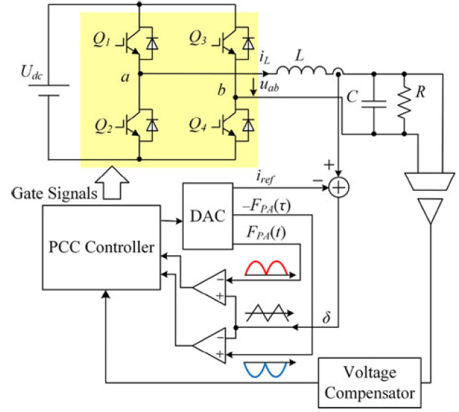 Figure.1. Diagram of a stand-alone inverter with internal parabolic current loop and external voltage loop
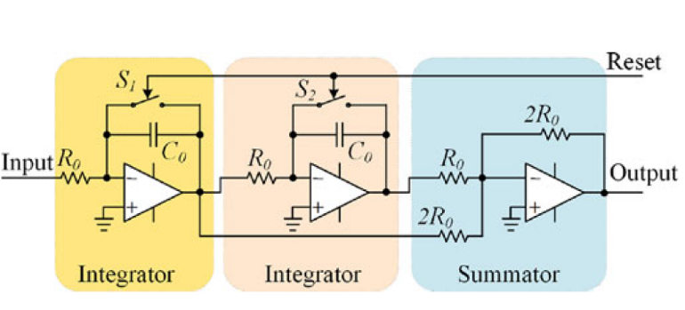 Figure.2. Parabolic carrier waveform generator
3. Model the Proposed Stand-Alone Inverter with Two Loop controllers
3.1. Inverter model
The procedure to select a stand-alone Photovoltaic (PV) system presented in [3]. Specifying and integrating PV components for a RES will include voltage and power choices to be made, stored, the PV modules themselves, with a vital link being the charge controller. This could be a DC-DC converter or DC-AC inverter [7]. In this section, the stand-alone inverter is considered. A single phase stand–alone inverter is shown as in fig.3, consisting of the DC voltage source, inverter full bridge, controlled by a Sinusoidal Pulse Width Modulation (SPWM) generator, the output voltage of DC/AC inverter needs a filter to attenuate switching harmonic components, thus, the LC filter is used. The mathematical model of a single-phase inverter with LC filter is given by applying KVL and KCL in [3, 27, 28] as follows: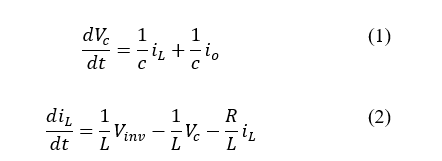
At no load the transfer function between the output voltage and the input voltage can be given where the output voltage Vo is equal to the voltage on capacitor Vc:
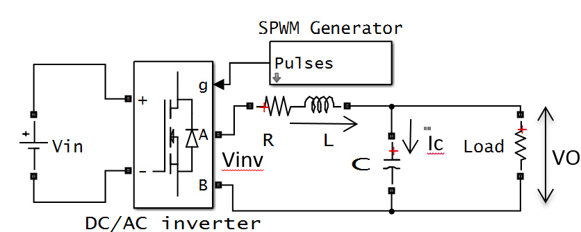 Figure.3. Power circuit of stand-alone inverter
3.2. Design optimal control of a stand-alone inverter
The capacitor current is controlled by an inner loop as shown in fig.4 where the inductor with parasitic resistance is used.
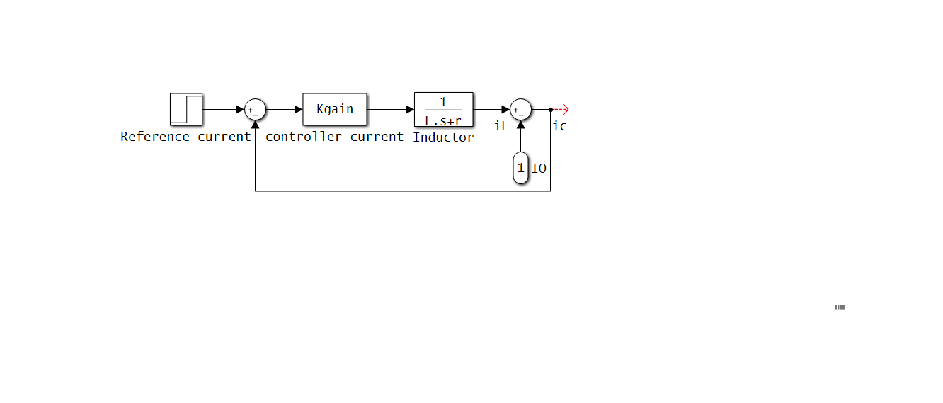 Figure.4. Block diagram of capacitor current controller
In this paper, two loop controllers are proposed to control the output voltage. The first loop is a capacitor current controller and the second loop is the output voltage of the stand-alone inverter controller as depicted in fig.5.
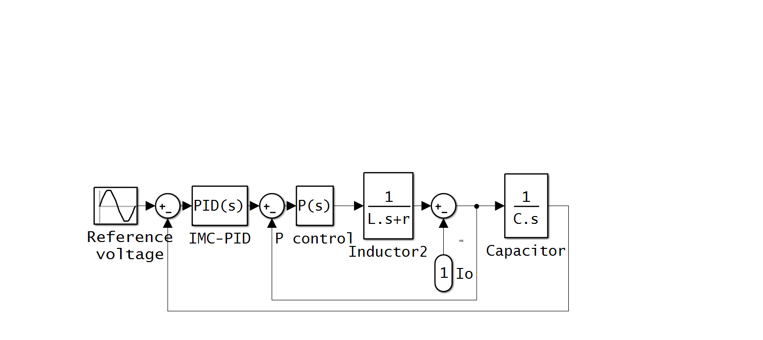 Figure.5. Full block diagram of stand-alone inverter
The parameters of the numerical model of the stand-alone inverter are selected based on [6], with an ideal of the full bridge assumed also the effect of grid current is neglected.
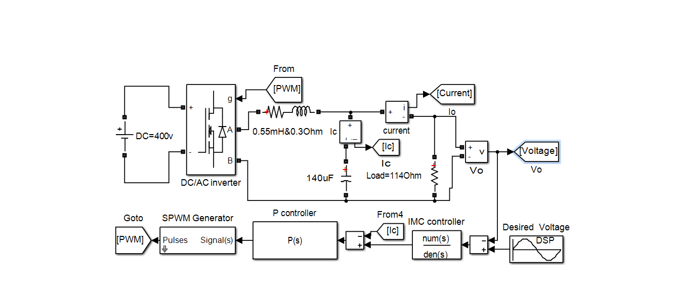 Figure.6. Circuit diagram of stand-alone inverter with proposed controller
3.3. Simulation Results
To evaluate the performance of the proposed controller of a stand-alone inverter, the output voltage and current were measured as in fig.7. It is clear that the stand-alone inverter works at unity power factor. The load is selected to be114 Ω to compare with experimental results.
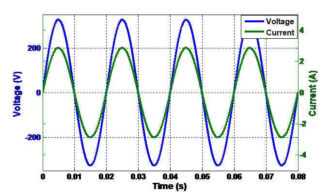 Figure.7. Output voltage and current of stand-alone inverter
The THD of output current was analysed in the frequency domain. The spectral analysis is shown in fig.8. The THD of the output is minimal and complied with IEEE-standard analyses of the output voltage of stand-alone inverter
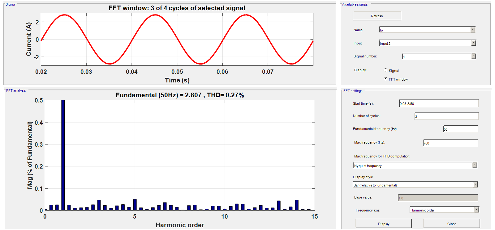 Figure.8. Output current of stand-alone inverter and its FFT analysis
The main issues of the stand-alone inverter are a fluctuation of the input voltage and variation of the load. In this paper, the variations of the load are only considered. A unit step with an ideal breaker is used to connect and disconnect the load, and a resistive load is varied to investigate the response of the system.
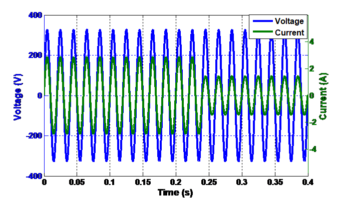 Figure.9. The response of stand-alone inverter to reduce the load
At 0.24s the unit step is selected to trip, therefore, the output current will decrease to half as shown in fig 9. The response of the stand-alone inverter is very fast and smooth to reduce the load. In fig.10 the output current responds to increases in the load and the output voltage may not be affected. This validates the robustness of the controller.
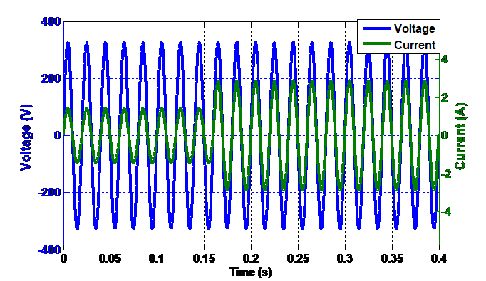 Figure.10. Smooth response of stand-alone inverter to increase the load
It is clear that the proposed controller of a stand-alone inverter has very smooth and fast response to variations of the load when the resistive load increases or decreases.
4. Experimentation works and Validation
4.1. Configuration of Sunny Island SI6.0H inverters as off-grid system
The Sunny Island (SI 6.0H) inverter is taken as out working example, which is a bidirectional converter. It can be operated on the island (off grid) where it forms a stand-alone system providing active and reactive power and on-grid modes. This section will test the power quality of the off-grid system and understanding the performance of SI 6.0H inverter and to compare with the power quality of the utility network. The power quality should meet the IEEE 519-2014 standard [29]. In this experiment, the SI 6.0H inverter with battery storage was used to supply the variable resistive loads.
4.2. Testing power quality of off-grid and utility network
Experimental work was conducted to test the power quality in the laboratory. The two resistors, each resistor is 228 Ω, were used. Those resistors were connected in parallel to give 114 Ω. The SI 6.0H inverter was configured in an off-grid mode and used to supply resistive loads. The output voltage and current of SI 6.0H inverter are analyzed where it supplied the resistive loads. The THD of the output voltage and current are measured by using a Power Analyzer and also the waveform components are analyzed by using FFT analysis. The FFT is used to evaluate the performance of a stand-alone inverter, as presented in [30]. The Same resistive loads are supplied from the grid and the same procedures are carried out in order to compare the acquired results of power quality of the grid with the off-grid system.
4.3. Experimental Results
In the stand-alone inverter, the output voltage and frequency should be fixed (do not change such as 230 V, 50Hz). The SI 6.0H inverter was set up as an off-grid system with battery storage.
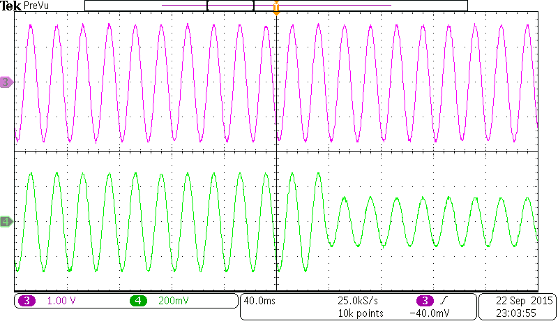 Figure.11. Test response of sunny island inverter to step down of the resistive load, trace 3 output voltage [200V/Div.] and trace 4 current loads [10A/Div.]
The oscilloscope is triggered to observe the response of the output current and voltage to variations of the resistive load. It is clear that the output voltage does not affect by variation of the load, while the current varies according to the variation of resistive loads. Moreover, when the load increases the current has small distortion for a short period of time as shown in fig 11 and fig. 12.
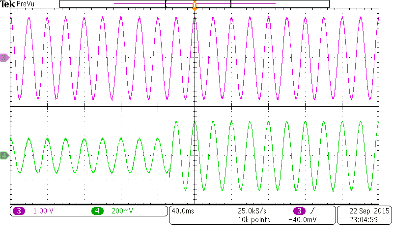 Figure.12. Step up the resistive load of off-grid sunny island and its response, trace 3 output voltage [200V/Div.] and trace 4 current loads [10A/Div.]
Therefore, the spectral analysis of the output current and voltage of SI 6.0H inverter is analysed as shown in fig.13 and fig .14, respectively.
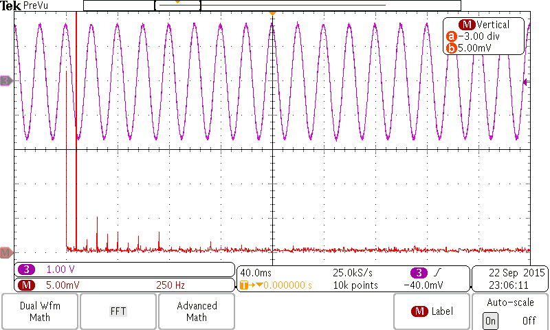 Figure.13. The output voltage of off-grid system and its FFT analysis [200V/Div.] and THD=1.6%
The grid is used to supply the same resistive load. The voltage and current on the resistive load were measured as shown in fig.15. From the waveforms of network voltage and load current, it is clear that the network utility has high harmonic components such as the third harmonic. Therefore, those waveforms are analysed and measured by using power analysed to evaluate the power quality of the network
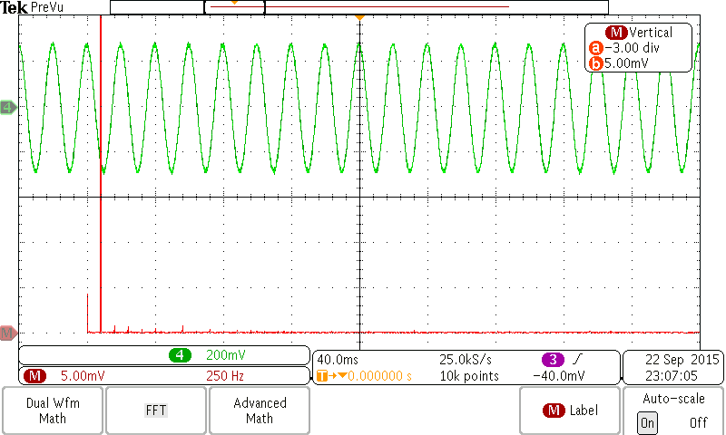 Figure.14. The waveform of output current [10A/Div.] of the off-grid system and its FFT where the THD=1. 123%
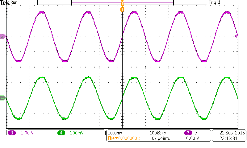 Figure.15. Trace 3 is the network voltage [200V/Div.] and trace 4 is the load current [10V/Div.]
Fig 16 shows the grid voltage and its spectrum. It is interesting to compare this waveform with the waveform of the output voltage of SI 6.0H inverter. The third, fifth and seventh harmonic of the grid voltage is higher than the output voltage of SI 6.0H inverter.
The THD of the output current of SI 6.0H inverter is less than the THD of the network when we compare between fig. 14 and fig.17. This is due to the different loads connected to the network, such as inductive load and resistive load are supplied from the network and those produce the harmonic components in the network. In addition, the line impedance and the renewable energy such as solar energy causes a distortion in the network.
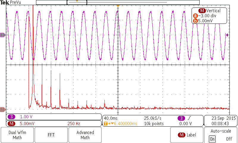 Figure.16. The Output voltage of the network and its FFT analysis[200V/Div.] and THD=2.5%
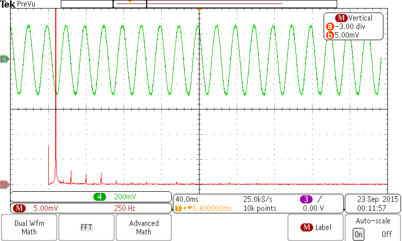 Figure.17. The waveform of current when it is supplied by a network [10A/Div.] and it’s spectrum analyser where the THD=1. 5%
4.4. Limitations of Stand-Alone System
The ripple current in DC side of inverter is the main problem. This ripple current reduces the battery lifespan or fuel cell life as can be seen in fig.18. This problem has been discussed in depth in [31].
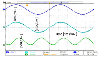 Figure.18. Trace 1 is the grid voltage, trace 2 is the current injected into the battery from the solar system, and trace 4 is the ripple current injected into the storage battery that has DC and AC components
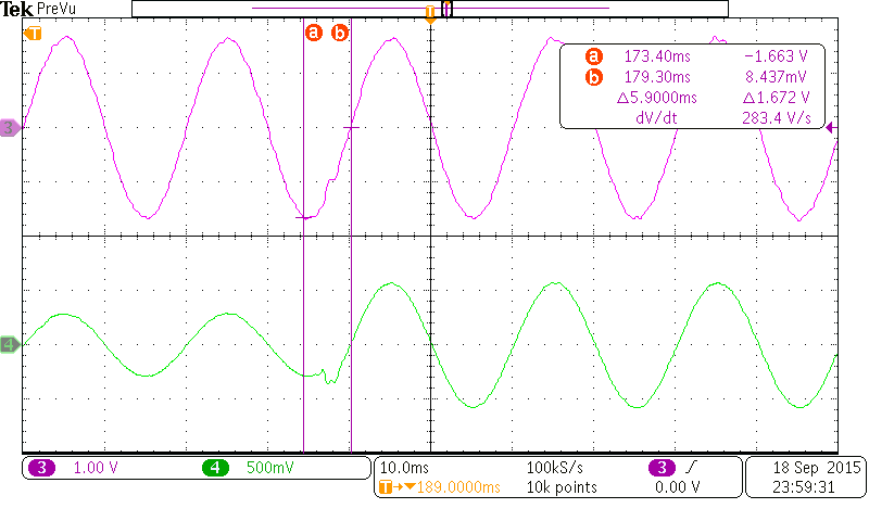 Figure.19. Response of the output current of the Mini-Grid in trace 4 and voltage in trace 3
The main issues of the stand-alone inverter relate to the input voltage fluctuation and load variation, with Munsell [32] recently presenting the potential challenges for networks as follows:
1- Growth of distributed energy sources
2- Changes in the customer preferences
3- Expansion of energy market services
4- Increasing regulation
Due to the above, grid reliability remains as critical as ever, which underscores it as a subject for future research.
5. Further Investigations to Reduce the Ripple Current and Suggestions
5.1. Reducing Current Ripple at Battery Side
Reducing input current ripple in a fuel cell system with load inverter was proposed by Changrong and Jih-Sheng to increase fuel cell lifespan [33]. The active control technique was incorporated with a current control loop to reduce this ripple even though; the harmonic analysis of the output current to evaluate the performance may not be considered. Also, the system has a four stage, which causes a complexity. The virtual resistor with an LC filter for PWM inverter was used to damp the transient oscillations by Dahono et al.[34]. Nevertheless, the virtual resistor gives nice waveforms for the output voltage and current, there are limitations as follow: the DC voltage source was assumed a constant and no ripple; although the THD of the output voltage was reduced, the value of the inductor is slightly large; FFT analysis may not take into account to evaluate the performance of the system and the output load was assumed to be source current. In fact, the virtual resistor is very good idea to reduce the losses. This requires an additional control load such as capacitor current loop as presented in [1]. Attempt for improving the battery life of the stand-alone solar system was presented by Das and Agarwal [35]. Despite this system can be used with solar PV, ultracapacitor bank, fuel cell and has a good dynamic response, but there are limitations which are:
- The system is complex because of the used bi-directional DC-DC converter, for battery DC-DC regulated for PV panel and inverter to the converter from DC-AC voltage.
- In the DC link, there is a ripple current which may not take into account. Also, the ripple current that goes the battery or flows from battery do not demonstrate or present since the title of this study was enhancing battery life.
- Also, this system was used for three phase inverter, which could be different with single phase inverter.
The AC mini-grid that presented in [1] is less stage of power. Hence, the losses are low and efficiency is high.
5.2. The Key Findings and Suggestions
To design the stand-alone inverter, the following procedures are required:
- Determine the value of the output power that is required to be delivered from the stand-alone
- Determine the power quality of the output voltage and current
- Based on the required power, the various elements of an inverter that include the switches and the LC filter will be selected.
- Based on the power quality, the LC filter will be characterised and the control approach will be implemented.
- From point of view, the two loops of the control system should be used as presented in [1] to improve the overall system despite the cost and a little complex control system.
- After designing the stand-alone inverter, it should be tested by the nonlinear load such as full-wave rectifier circuits that has to exaggerate the THD even further and thereafter the THD of the output current and voltage should be evaluated and compared with IEEE 519-2014 standard.
5.3. Applications of Stand-Alone Inverter
The inverter is a critical component used to convert Direct Current (DC) power output from the solar panels or batteries into Alternative Current (AC) for AC appliances. There are many applications for stand-alone inverter such as the PV solar system to pump the water in remote areas as shown in the figure below [36].
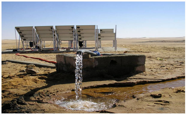 Figure.20. PV Water Pumping Beer Tssawa
Therefore, the solar water pump inverter is widely used for many applications such as irrigation system, livestock watering, or in remote areas with battery backup that are suitable for the solar home system, rural and village electrification. In general, stand-alone inverter or off-grid power systems operate independently of the grid and are most often used in isolated areas, where the stand-alone inverter provides a more affordable and reliable source of electricity.
5.4. Impact of global warming
Effect global warnings in the earth were summarized by Boso as follows [37]:
- The world is the glaciers and polarise will be gradually melted, which will cause a problem for 100 million people because they live within 91.44 centimetres of sea water level.
- Some animal will gradually extinct, such as polar bears.
- A tropical climate will spread the diseases due to more moisture.
- Hurricanes, tornados, heavy rains and floods will expect increase due to heavy moisture and circulation of the air.
- Tropical countries may severe of droughts which will affect and damage agriculture and also cause problems for fresh water.
However, this study was suggested that the use renewable energy instead fossil fuels can mitigate some of the global warms issues, which was assumed as the first step to solving this problem.
6. Conclusion
This paper presents the power quality of an off-grid (SI 6.0H inverter) system and power quality of the national grid in the UK. The off-grid system has less distortion of waveforms than the grid. The numerical model of a stand-alone inverter is modelled with two loops. The inner loop is a capacitor current control and the outer loop is the output voltage controller. The inner loop does not change the tracking features of the closed-loop system; it does not only improve the performance of linear load but also improving the performance of the nonlinear loads. The output waveform of model inverter and analysis are presented in this paper. The power quality is improved and gives an excellent response to the variations of the load. The simulation results match the experimental results. In critical load or devices that require a pure power, such as magnetic resonance imaging- medical devices, the off-grid system is suitable to protect those devices from abnormal voltage and frequency. The recent publications of stand-alone inverter were critically reviewed and the key findings with suggestions were given to improve the overall system. Future work will be analysed the impact of fluctuation of the input voltage of a stand-alone inverter. In addition, the stand-alone inverter will be tested by the nonlinear load such as full-wave rectifier circuits and thereafter the THD of the output current and voltage will be assessed.
Conflict of Interest
The authors declare no conflict of interest.
Acknowledgment
The experimental work presented in this paper was conducted at the Department of Engineering, University of Leicester, UK, while the numerical analysis was conducted in the Institute of Energy and Sustainable Development (IESD) at De Montfort University, Leicester, UK.
- Algaddafi, N. Brown, R. Gammon, S. A. Altuwayjiri, and M. Alghamdi, “Improving off-grid PV system power quality, and comparing with grid power quality,” IEEE in 2016 International Conference on Electronics, Information, and Communications (ICEIC), 1-6(2016).
- -S. Lee, S. Chiang, and J.-M. Chang, “H∞ loop-shaping controller designs for the single-phase UPS inverters,” IEEE Transactions on Power Electronics, 16: 473-481 (2001).
- Wenfang, H. Qun, and X. Yingnian, “Study on IMC-PID control for single-phase voltage-source inverters,” IEEE 6th International in Power Electronics and Motion Control Conference, 1514-1518 (2009).
- Zhou, K.-S. Low, Y. Wang, F.-L. Luo, B. Zhang, and Y. Wang, “Zero-phase odd-harmonic repetitive controller for a single-phase PWM inverter,” IEEE Transactions on Power Electronics, 21:193-201 (2006).
- Zhang, L. Peng, J. Xiong, and J. Chen, “State-feedback-with-integral Control plus Repetitive Control for PWM Inverters,” IEEE in Proceedings of the Chinese Society of Electrical Engineering, 56-62 (2006).
- Mohan, T. M. Undeland, and W. P. Robbins, Power Electronics: Converters, Applications, and Design: John Wiley & Sons, 2003.
- -J. Wai, W.-H. Wang, and C.-Y. Lin, “High-performance stand-alone photovoltaic generation system,” IEEE Transactions on Industrial Electronics, 55: 240-250 (2008).
- M. Abdel-Rahim and J. E. Quaicoe, “Analysis and design of a multiple feedback loop control strategy for single-phase voltage-source UPS inverters,” IEEE Transactions on Power Electronics, 11: 532-541 (1996).
- Wang and Y. W. Li, “Parabolic PWM for current control of voltage-source converters (VSCs),” IEEE Transactions on Industrial Electronics, 57: 3491-3496 (2010).
- Zhang, B. Gu, J. Dominic, B. Chen, C. Zheng, and J.-S. Lai, “A dead-time compensation method for parabolic current control with improved current tracking and enhanced stability range,” IEEE Transactions on Power Electronics, 30: 3892-3902 (2015).
- Zhang, J. Dominic, B. Gu, B. Chen, C. Zheng, and J.-S. Lai, “Implementation of parabolic current control for dual-carrier PWM,” IEEE in 2015 Applied Power Electronics Conference and Exposition (APEC), 1487-1492 (2015).
- Zhang, R. Born, B. Gu, B. Chen, C. Zheng, X. Zhao, et al., “A Sensorless Implementation of the Parabolic Current Control for Single-Phase Stand-Alone Inverters,” IEEE Transactions on Power Electronics, 31: 3913-3921 (2016).
- M. Smedley and S. Cuk, “One-cycle control of switching converters,” IEEE transactions on power electronics, 10: 625-633 (1995).
- M. Smedley, L. Zhou, and C. Qiao, “Unified constant-frequency integration control of active power filters-steady-state and dynamics,” IEEE Transactions on Power Electronics, 16: 428-436 (2001).
- A. Froeschle, “Current controlled two-state modulation,” ed: Google Patents, (1984).
- Malesani and P. Tenti, “A novel hysteresis control method for current-controlled voltage-source PWM inverters with constant modulation frequency,” IEEE Transactions on Industry Applications, 26: 88-92 (1990).
- Malesani, L. Rossetto, and A. Zuccato, “Digital adaptive hysteresis current control with clocked commutations and wide operating range,” IEEE transactions on industry applications, 32:316-325 (1996).
- Gupta, “Generalized frequency domain formulation of the switching frequency for hysteresis current controlled VSI used for load compensation,” IEEE Transactions on Power Electronics, 27: 2526-2535 (2012).
- Yao and L. Xiao, “Two-switch dual-buck grid-connected inverter with hysteresis current control,” IEEE Transactions on Power Electronics, 27: 3310-3318 (2012).
- Mao, X. Yang, Z. Chen, and Z. Wang, “A hysteresis current controller for single-phase three-level voltage source inverters,” IEEE Transactions on Power Electronics, 27: 3330-3339 (2012).
- Yao and D. G. Holmes, “A simple, novel method for variable-hysteresis-band current control of a three phase inverter with constant switching frequency,” IEEE in Industry Applications Society Annual Meeting, 1993., Conference Record of the 1993, 1122-1129 (1993).
- Buso, S. Fasolo, L. Malesani, and P. Mattavelli, “A dead-beat adaptive hysteresis current control,” IEEE Transactions on industry applications, 36: 1174-1180 (2000).
- Abdel-Salam, A. Ahmed, A. El-kousy, K. Sayed, M. Amery, M. Swify, et al., “On the design and operation of a standalone residential PV system in Egypt,” 2013 International Conference on Clean Electrical Power (ICCEP), 659-664 (2013).
- A. A. Coelho, P. C. Cortizo, and P. F. D. Garcia, “Small-signal stability for parallel-connected inverters in stand-alone AC supply systems,” IEEE Transactions on Industry Applications, 38: 533-542 (2002).
- Vahedi, P. A. Labb, x00E, and K. Al-Haddad, “Sensor-Less Five-Level Packed U-Cell (PUC5) Inverter Operating in Stand-Alone and Grid-Connected Modes,” IEEE Transactions on Industrial Informatics, 12: 361-370 (2016).
- Algaddafi, N. Brown, G. Rupert, and J. Al-Shahrani, “Modelling a Stand-Alone Inverter and Comparing the Power Quality of the National Grid with Off-Grid System,” IEIE Transactions on Smart Processing and Computing, 5: 35-42 (2016).
- F. Sultani, “Modelling, Design and Implementation of DQ Control in Single-Phase Grid-Connected Inverters for Photovoltaic Systems used in Domestic Dwellings,” De Montfort University, (2013).
- Monfared, S. Golestan, and J. M. Guerrero, “Analysis, design, and experimental verification of a synchronous reference frame voltage control for single-phase inverters,” IEEE Transactions on industrial Electronics, 61: 258-269 (2014).
- , IEEE Recommended Practice and Requirements for Harmonic Control in Electric Power Systems – Redline, available at: http://ieeexplore.ieee.org/xpl/articleDetails.jsp?arnumber=6826459&filter=AND(p_Publication_Number:6826457[accessed:01/01/2015], 1-213 (2014).
- O. Neacsu, Power-switching converters: medium and high power: CRC press, (2014).
- Algaddafi, J. Alshahrani, S. Hussain, K. Elnaddab, E. Diryak, and I. Daho, “Comparing The Impact of the Off-Grid System and On-Grid System On a Realistic Load.” Proceeding in 32nd European Photovoltaic Solar Energy Conference and Exhibition, Munich, German, (2016).
- Munsell, “9 Projects Defining the Next-Generation Electricity System, available at: http://www.greentechmedia.com/articles/read/9-projects-defining-the-next-generation-electricity-system?utm_content=bufferfe6de&utm_medium=social&utm_source=facebook.com&utm_campaign=buffer [accessed:24/03/2016].
- Changrong and L. Jih-Sheng, “Low Frequency Current Ripple Reduction Technique with Active Control in a Fuel Cell Power System with Inverter Load,” IEEE Transactions on Power Electronics, 22: 1429-1436 (2007).
- A. Dahono, Y. R. Bahar, Y. Sato, and T. Kataoka, “Damping of transient oscillations on the output LC filter of PWM inverters by using a virtual resistor,” IEEE in 4th International Conference on Proceedings Power Electronics and Drive Systems, 403-407 (2001).
- Das and V. Agarwal, “A novel control strategy for stand-alone solar PV systems with enhanced battery life,” IEEE in Applied Power Electronics Conference and Exposition (APEC), 2014 Twenty-Ninth Annual IEEE, 2880-2887 (2014).
- Ekhlat, I. Salah, and N. Kreama, “Energy efficiency and renewable energy. Libya–National Study,” General Electric Company of Libya (GECOL), (2007).
- K. Bose, “Global Warming: Energy, Environmental Pollution, and the Impact of Power Electronics,” IEEE Industrial Electronics Magazine, 4: 6-17 (2010).