
Design of an Automatic Forward and Back Collision Avoidance System for Automobiles
Volume 3, Issue 1, Page No 205-212, 2018
Author’s Name: Tasneem Sanjanaa), Ferdus Wahid, Mehrab Masayeed Habib, Ahmed Amin Rumel
View Affiliations
Faculty of Electrical and Electronic Engineering, American International University-Bangladesh (AIUB), 1213, Bangladesh
a)Author to whom correspondence should be addressed. E-mail: tsanjana909@gmail.com
Adv. Sci. Technol. Eng. Syst. J. 3(1), 205-212 (2018); ![]() DOI: 10.25046/aj030124
DOI: 10.25046/aj030124
Keywords: Forward collision avoidance system, Rear collision avoidance system, ATMEGA32, Sharp Distance Sensor, Motor driver, Actuator

Export Citations
This paper is the extended reflection of work originally presented in conference of Electrical, Computer and Communication Engineering (ECCE)-CUET 2017, entitled “Automated Anti Collision System for Automobiles”. Automated collision avoidance system is a trending technology of science in automobile engineering. The aim of this paper is to design a system which will prevent collision from the front as well as the back for automobiles. This paper gives an overview of secure and smooth journey of car (vehicles) as well as the certainty of human life. This system is controlled by microcontroller ATMEGA32. Two Sharp distance sensors are used to detect object within the danger range where one is for front detection and other is for back detection. A crystal oscillator is used to produce the oscillation and generates the clock pulse of the microcontroller. An LCD and a GLCD are used to give information about the safe distance for front and rear respectively, and a buzzer is used as alarm. An actuator is used as automatic brake and inside the actuator there is a motor driver that runs the actuator. For coding “microC PRO for PIC” is used and “Proteus Design Suite Version 8 Software” is used for simulation.
Received: 14 November 2017, Accepted: 09 January 2018, Published Online: 30 January 2018
1. Introduction
All of the greatest achievement of the science, automobile is the most probably the one, which significantly changed human life. A collision avoidance system is a current emerging technology in the field of automobile. It is also known as pre-crash system, forward collision warning system or collision mitigating or car anti-collision system. An automated car anti-collision system is an automobile safety system design to reduce the accidents as road traffic accidents are the largest cause of injury-related deaths worldwide .When driver himself is not concentrating on driving or any other parameters, that time it may cause damage to vehicle (car) as well as a life, that time automated ant-car collision device can play an effective role regarding the danger ahead. An automated anti-collision system device is placed within a car to warn its driver of any dangers that may lie ahead on the road. Once the detection is done this system either provide a warning to the driver when there is an imminent collision or take action autonomously without any driver command (by braking or steering both). This system runs by microcontroller that detects obstacle with speed sensor and stops the vehicle by giving instruction to the actuator. [1].
2. Literature Review
In 2003, Honda introduced the first pre-crash system with autonomous braking. In 2003 Toyota added an “automatic partial pre-crash braking system” to the Celsior36. In 2006 Audi introduced “Braking guard” radar-assisted forward collision warning on AudiQ7. But these could not put a satisfactory performance. These all were not fully automated. In 2009, the U.S. National Highway Traffic Safety Administration (NHTSA) had begun studying to make frontal collision warning systems and lane departure warning systems. In 2012 a research by the Insurance Institute for Highway Safety examined how particular features of crash-avoidance systems affected the number of claims under various forms of insurance coverage. This indicates that two crash-avoidance features provide the biggest benefits; these are (a) autonomous braking that would brake on its own when the driver would not alert to avoid a forward collision and (b) adaptive headlights that would shift the headlights in the direction to the driver steers. At the circa 2012 stage of development, it has found from this research that lane departure systems is not helpful and perhaps harmful. Periodically anti-car collision features are rapidly making their way into the new vehicle fleet. Many car companies like BMW, Audi, Mercedes- Benz , Ford, Toyota, Volvo developed vehicle collision avoidance system from 2003-2009, but not necessarily they were all time effective.[1] Few years back, some research were carried out on car anti-collision system device using ad hoc wireless network, V2V communication, GPS and radar implementation but all this effort were informatory in type which would give signal to the driver or produced some buzzes or sounds only but finally action would be taken by the driver own self in which there were quite chances of the collision. [2] Since the emergence of mechanical vehicles, road safety has been a major concern, the automated anti-car collision system has gained increasing attention in the last three years. As a result, various automated anti car collision system have originated for assuring safety than the existing system. Research of the Queensland department of Transport and Main Roads has revealed that installation of anti-collision technology could reduce 20 to 40 percent in terms of number and severity of fatal crashes and 30-50 percent of all injuries. Thus it is the main aim to ensure the safety of human life during the collision, the U.S National High Way Traffic Safety Administration has decided to make the pre-crash system mandatory for vehicles. In similar way all new vehicles in Europe will have advanced emergency automated braking system installed by November,2015. A group of automakers and suppliers companies including General Motor(GM), Ford Motor, Nissan Motor are doing research of this automated vehicles collision avoidance system at the University of Michigan. General Motor company has a plan to install this automated vehicles avoidance system in their cars by next two years. Toyota has already given an official announcement that they are going to give this automated vehicles avoidance system in their Toyota and Lexus models by 2017. On the other hand, BMW has already introduced satisfactory and effective anti-car collision system on BMW 7series in 2012. Volvo company has launched this system in Volvo FH by February 2013. Also car company Renault introduced automated active braking system on Renault EspaceV, in October 2014 as well as Volkswagen Passat introduced too on Volkswagen Passat/B8 in 2014. [2] [3] Today, automated anti car collision system generally has camera sensor, distance sensor, actuator, buzzer to detect and warn the drivers of any danger lie ahead on the road, it could be a car, human, pedestrian or any stationary object just as tree or pole etc.
3. System Overview
The block diagram of proposed system is given in Fig.1.Advantage of proposed block diagram over existing technologies is, this system will provide forward collision protection as well as helps to avoid rear collision by displaying messages to the vehicles coming from the back regarding to slow down their vehicle. Here microcontroller does the prime work and it controls the entire task. Two distance sensors are connected to the microcontroller. A LCD, A GLCD and an alarming device are also connected to the microcontroller. A Motor Driver is connected with micro controller to operate an actuator, as actuator needs high current to turn on and microcontroller can’t provide this amount of current so motor driver will provide high current to actuator to turn on when it’s needed. Distance sensors will be placed in front and back side of a car. They will sense the distance of vehicle in front and rear of the car and send this information to microcontroller. Microcontroller will compare this distance with some preset distances. If the measured distance from the front distance sensor crosses the preset safe distance value, microcontroller will send command to LCD to display close distance and also to write value of that exact distance, At the same time microcontroller will send a pulsating signal to buzzer and buzzer will be buzzed according to that signal. If the measured distance by the front distance sensor crosses the preset value of close distance in microcontroller, microcontroller will tell LCD to show critical distance and the value of that corresponding distance measured by the sensor.
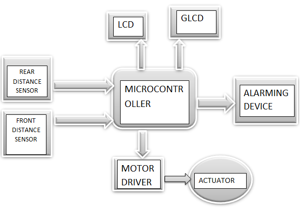 FIG.1. Block diagram of forward and back collision avoidance system for automobiles
At the same time a continuous signal will be send to buzzer and it will buzz continuously to notify the driver that vehicle is exceeding close distance and it’s forwarding towards critical distance. Whenever vehicle crosses critical distance and entered into the distance at which collision is must if the car isn’t slow down, that moment microcontroller will send signal to motor driver to turn on the actuator and it will stop the car automatically, at the same time LCD will “show actuator on” with distance information. Here, actuator itself works as a brake. For rear distance sensor it will sense the distance of the incoming vehicle and it will sent information to micro controller, if the distance exceed the safe distance value microcontroller will instruct GLCD to display slow down along with distance information, and if the incoming vehicle crosses critical distance microcontroller will instruct GLCD to display “Emergency! Stop” along with distance information to the driver of the incoming vehicle from the back. GLCD could be placed at the rear glass or just above the registration plate of the car containing this proposed safety technology.
4. Preparation to Proteus model
In this section components that were used for simulation and connection diagram has been explained.
4.1. ATMEGA32
ATMEGA32 is the high-performance, low-power Microchip 8-bit AVR RISC-based microcontroller combines 32KB ISP flash memory with read-while-write capabilities, 1KB EEPROM, 2KB SRAM, 54/69 general purpose I/O lines, 32 general purpose working registers, a JTAG interface for boundary-scan and on-chip debugging/programming, three flexible timer/counters with compare modes, internal and external interrupts, serial programmable USART, a universal serial interface (USI) with start condition detector, an 8-channel 10-bit A/D converter, programmable watchdog timer with internal oscillator, SPI serial port, and five software selectable power saving modes. The device operates between 1.8-5.5 volts. By executing powerful instructions in a single clock cycle, the device achieves output through approaching 1 MIPS per MHz, balancing power consumption and processing speed. [4]
4.2. Sharp Distance Sensor: Model (GP2Y0A21):
A sensor is an electrical device which is used to measure physical properties and gives corresponding electrical output which is a transmitting impulse as for measurement or control for operation. In this model for measuring the distance of a vehicle Sharp Distance Sensor (GP2Y0A21) is used. Sharp Distance sensor follows triangulation measuring method for measuring distance of an object in front of it, It transmits an IR (Infrared Ray), if any obstacle is present in the path of that IR ray it will bounces back to the sensor and that’s how distance is measured. Output of this sensor is analog and this output varies a range from 3.1V at 10cm to 0.4V at 80cm.
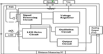 FIG.2.Internal Block Diagram of Sharp Distance Sensor [1]
FIG.2. indicates that this sensor contains IR LED armed with lens which discharges narrow light beam, after reflecting from the object, the beam will be directed through the second lens on a position-sensible photo detector (PSD) and the conductivity of PSD depends on the point where the beam falls, finally conductivity converts to voltage and voltage digitalizes by Analog to digital converter (ADC) [5]. Sharp Distance sensor utilize following equations to convert Distance into digitalized voltage with the help of ADC, and the relation between distance and the Voltage is
![]() Where, distance is in centimeters.
Where, distance is in centimeters.
k is corrective constant (fund using tial-and-error method)
ADC is digitalized value of voltage.
A is linear member (value is determined by the trend line
equation)
b is free member (value is determined by the trend line equation).
So, distance d can be expressed from the formula [6]:
d = (1 / (a * ADC + B)) – k (2)
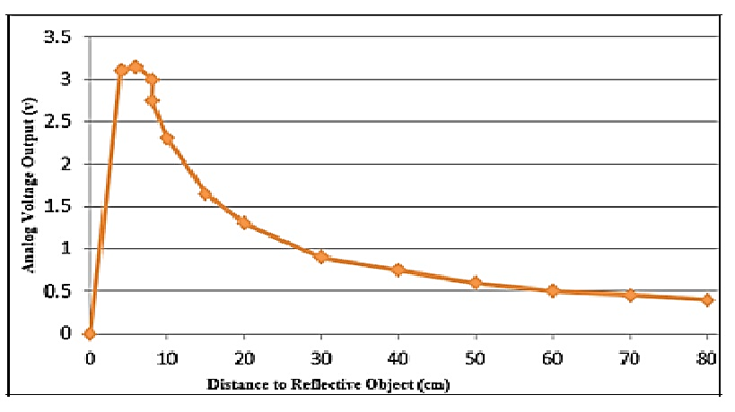 FIG.3.Internal Block Diagram Of Sharp Distance Sensor Voltage-distance characteristics graph of Sharp Distance Sensor (GP2Y0A21K) [1]
If a graph is plotted using equation (2) it will look like FIG.3. After analyzing this graph it can be concluded that the output voltage of the Sharp distance sensor is decreasing with the increased distance, which indicates an inversely proportional relation between distance and output voltage of sharp distance sensor.
4.3. Linear Actuator:
Linear actuator is a device which converts circular motion produced by a conventional electric motor into linear motion. Linear actuators are used in machine tools and industrial machinery, in computer peripherals such as disk drives and printers, in valves and dampers, and in many other places where linear motion is required. Hydraulic or pneumatic cylinders inherently produce linear motion. Many other mechanisms are used to generate linear motion from a rotating motor. In the majority of linear actuator designs, the elementary principle of operation is an inclined plane. The threads of a lead screw act as a continuous ramp that consents a small rotational force to be used over a long distance to complete the movement of a large load over a short distance. The system converts rotary motion (in the form of an electric motor) to linear motion. When an electrical source is applied to the motor, the thread shaft is driven and the nut rides up and down the shaft in the corresponding direction. This action delivers an extension and retraction capability for tasks requiring a linear displacement. Note that in this example the nut and red tube do not rotate, merely “ride” the threads on the spinning shaft up and down. [7]
4.4. Crystal Oscillator (16 MHz):
A crystal oscillator is an electronic oscillator circuit which uses in the mechanical resonance of a vibrating crystal of piezoelectric material to create an electrical signal with a very precise frequency and this frequency is usually used to keep track of time (as in quartz wristwatches), to provide a stable clock signal for digital integrated circuits, and to alleviate frequencies for radio transmitters and receivers, The most common type of piezoelectric resonator used is the quartz crystal, so oscillator circuits incorporating them became known as crystal oscillators but other piezoelectric materials including polycrystalline ceramics are used in similar circuits. [8]. A crystal is a solid in which the constituent atoms, molecules, or ions are packed in a repeatedly ordered, repeating pattern extending in all three spatial dimensions. Almost any object made of an elastic material could be used like a crystal, with appropriate transducers, since all objects have natural resonant frequencies of vibration. For example, steel is very elastic and has a high speed of sound. It was often used in mechanical filters before quartz. The resonant frequency depends on size, shape, elasticity, and the speed of sound in the material. High-frequency crystals are typically cut in the shape of a simple, rectangular plate. Low-frequency crystals, such as those used in digital watches, are typically cut in the shape of a tuning fork. For applications not needing very precise timing, a low-cost ceramic resonator is often used in place of a quartz crystal. When a crystal of quartz is suitably cut and mounted, it can be made to distort in an electric field by applying a voltage to an electrode near or on the crystal. This property is accepted as electrostriction or inverse piezoelectricity. When the field is removed, the quartz will generate an electric field as it returns to its previous shape, and this can generate a voltage. The result is that a quartz crystal behaves like a circuit composed of an inductor, capacitor and resistor, with a precise resonant frequency. Quartz has the further advantage that its elastic constants and its size change in such a way that the frequency dependence on temperature can be very low. The specific characteristics will depend on the mode of vibration and the angle at which the quartz is cut (relative to its crystallographic axes. Therefore, the resonant frequency of the plate, which depends on its size, will not change much, either. This means that a quartz clock, filter or oscillator will remain accurate. For critical applications the quartz oscillator is mounted in a temperature-controlled container, called a crystal oven, and can also be mounted on shock absorbers to prevent perturbation by external mechanical vibrations and oscillation.[8] In this design crystal oscillator is for to activate micro controller internal clock operating circuit.
4.5. Motor Driver (L293D):
L293D is a dual H-bridge motor driver integrated circuit (IC). Motor drivers act as current amplifiers since they take a low-current control signal and provide a higher-current signal. This higher current signal is used to drive the motors.L293D contains two inbuilt H-bridge driver circuits. In its common mode of operation, two DC motors can be driven simultaneously, both in forward and reverse direction. The motor operations of two motors can be controlled by input logic at pins 2 and 7 and 10 and 15. Input logic 00 or 11 will stop the corresponding motor. Logic 01 and 10 will rotate it in clockwise and anticlockwise. Enable pins 1 and 9 (corresponding to the two motors) must be high for motors to start operating. When an enable input is high, the associated driver gets enabled. As a result, the outputs become active and work in phase with their inputs. Similarly, when the enable input is low, that driver is disabled, and their outputs are off and in the high-impedance state. [9]
4.6. LCD Display (16X2):
LCD (Liquid Crystal Display) screen is an electronic display module and find a wide range of applications. A 16×2 LCD display is very elementary module and is very usually used in various devices and circuits. These modules are preferred over seven segments and other multi segment LEDs. The reasons is LCDs are economical, easily programmable, have no limitation of displaying special and even custom characters (unlike in seven segments), animations and so on. A 16×2 LCD means it can display 16 characters per line and there are 2 such lines. In this LCD each character is displayed in 5×7 pixel matrix. This LCD has two registers, namely, Command and Data. The command register stores the command instructions given to the LCD. A command is an instruction given to LCD to do a predefined task like initializing it, dissipating its screen, setting the cursor position, controlling display etc. The data register stores the data to be displayed on the LCD. The data is the ASCII value of the character to be displayed on the LCD. [10]
4.7. GLCD (AMPIRE128X64):
GLCD is a graphic liquid crystal display. AMPIRE (128X64) graphic LCD contains 128 coulombs and 64 rows. It can display data in (128×64) matrix. Graphical LCDs are different from the ordinary alphanumeric LCDS, like (16×1), (16×2), (16×4), (20×1), (20×2) etc. They (ordinary) can print only characters or custom made characters. They have a fixed size for displaying a character normally (5×7) or (5×8) matrix. Where as in graphical LCD we have 128×64=8192 dots each dot can be lit up as per coding or can make pixels with 8 dots that is 8192/8=1024 pixels, graphical LCD is controlled by two KS0108 controllers. A single KS0108 controller is capable of controlling 40 characters so for controlling a graphical LCD we need two KS0108 controllers and the 128×64 LCD is divided into two equal halves with each half being controlled by a separate KS0108 controller. [11] Special types of shapes or picture can be drawn in GLCD by exciting it DOTS.
4.8. MOSFET:
MOSFET is a three terminal semi-conductor device it consists of gate drain and source. It works in three region such as cutoff active and saturation. To use MOSFET as a switch it need to operate in active region and for amplification any input signal it will work in saturation region. Whenever a signal will be given in its gate it will activate. In this model MOSFET is used as a switch for alarming circuit (buzzer circuit). It’s used in a way that voltage across its drain to source is close to zero to make it work as a switch.
4.9. Proteus Model:
FIG.4 is the proteus model of an automatic forward and backward collision avoidance system. This microcontroller works within 20nsec. Its operating voltage range is: 2.0V to 5.5V. Two sharp distance sensors are used to measure the distance of the obstacle for front and rear respectively, crystal oscillator is also connected to the microcontroller, it produces the oscillation and generates the clock pulse of the microcontroller. There is a buzzer used as alarm and it is controlled by a MOSFET, microcontroller turns on the MOSFET which work as a switch for buzzer. A motor driver L293D is used for controlling the actuator. Actuator will be connected to the car braking system.
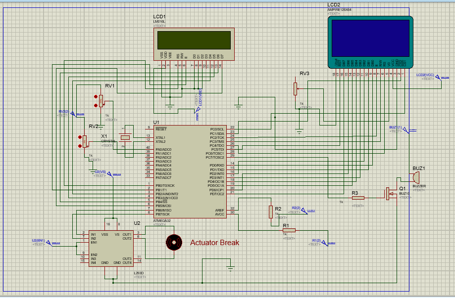 FIG.4. Proteus model of the system
From FIG.4 it is found that microcontroller pin7 (PB6/MISO) and pin8 (PB7/SCK) is connected to motor driver pin2 (IN1) and pin7 (IN2). From this connection of the configuration, motor driver gets command from microcontroller. 1k ohm resistors are connected to microcontroller pin30 and 32 with constant 5V DC for operating of microcontroller and ADC comparison respectively. ADC comparison is used in microcontroller because it will help microcontroller to process the measured distance by distance sensor in digital format. Microcontroller pin30 and 40 are connected to sharp distance sensors but there is no distance sensor device in Proteus so potentiometers are used instead of it. The highest readings of these potentiometers are 5k ohm and operating voltage +2.5V. Two port of actuator is connected to motor driver pin3 (OUT1) and pin6 (OUT2) A DC gear motor is used as an actuator in simulation for analyzing the motor driver behavior to actuator due to absence of an actuator in proteus model. Two ports of crystal oscillator are connected to microcontroller pin13 and pin12 is used for generating clock pulse of microcontroller. Here is a LCD display which pin11 (D4), pin12 (D5), pin13 (D6), pin14 (D7) are connected to microcontroller pin3 (PB2), pin4 (PB3/PGM), pin5 (PB4), pin6 (PBS) respectively, so that, LCD display can get signal from microcontroller and gives information about the obstacle.
Microcontroller pin29 (PC7) is connected to a MOSFET by a 1kohm resistor R2. Microcontroller itself cannot turn the buzzer on for this reason a MOSFET has been used. Microcontroller gives instruction to the MOSFET to turns the buzzer on and it operates at +12V. GLCD pin9-16 (DB0-DB7) is connected with microcontroller pin14-21 (PD0-PD7) which will give information regarding rear obstacle distance. GLCD control pins, 1(CS1), 2(CS2), 6(RS), 7(RW), 8(E), 17(RST) is connected to microcontroller pin22 (PC0),pin23 (PC1), pin26 (PC4),pin25 (PC3), pin24 (PC2),pin27 (PC5) respectively, so that GLCD can get signal from microcontroller and gives information about the distance which should be kept to avoid collision, or to stop to avoid collision towards the car approaching from the back. A program is written in MIKROC software, which is the instruction for microcontroller action and HEX file of that program is used for simulation.
5. Simulation and Result
From FIG.5.we can conclude that if there is a vehicle in front of a car containing this collision avoidance system at a distance of 35 cm microcontroller will command LCD to Display “safe distance “to the driver of the car, and at the same time if there is a vehicle approaching from rear and if it’s distance is 21 cm micro controller will instruct GLCD to display the distance information along with the message “Slow Down’’ to the incoming car from the back.
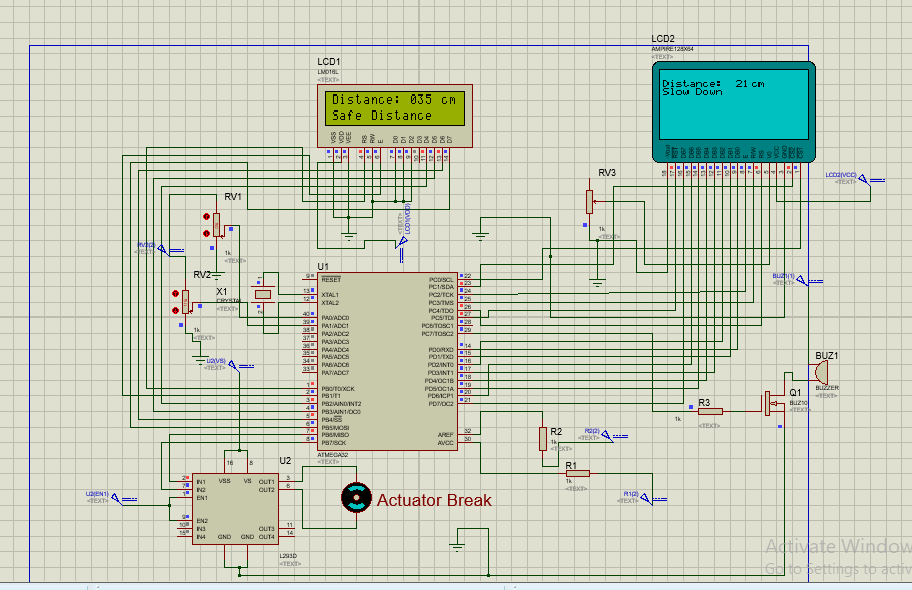 FIG.5. Result for safe distance for front and slow down distance for rear
From FIG.6. we can conclude that if there is a vehicle in front of a car containing this collision avoidance system at a distance of less than 26 cm microcontroller will command LCD to Display “Close Distance” to the driver of the car and microcontroller will send activation signal towards buzzer circuit, and at the same time if there is a vehicle approaching from rear and if it’s distance is less than 15 cm micro controller will instruct GLCD to display the distance information along with the message “Emergency! Stop’’ to the incoming car from the back.
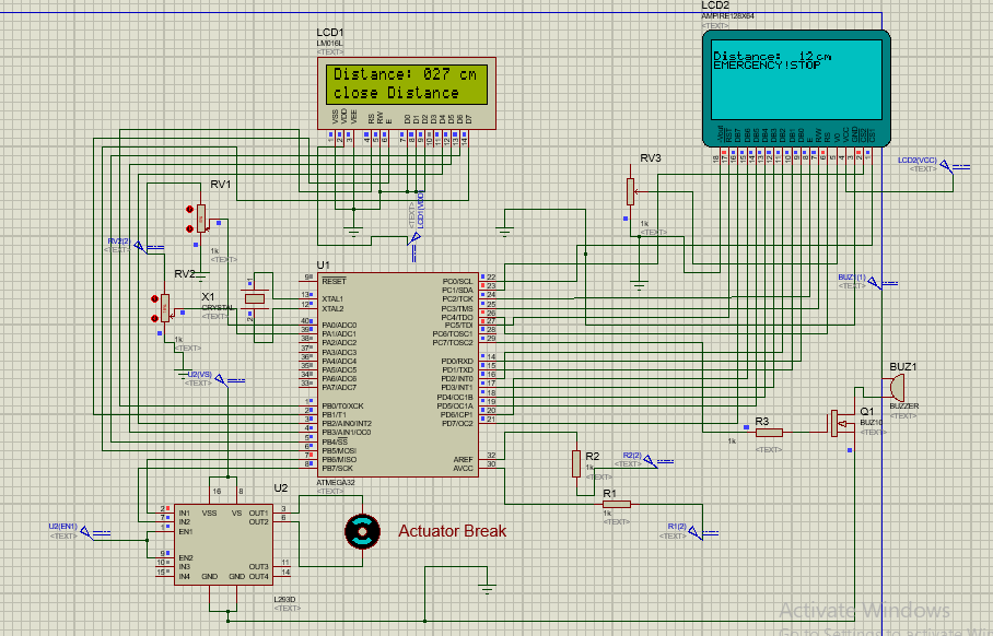 FIG.6. Result for close distance for front and emergency stop distance for rear
From FIG.7. shows that if there is a vehicle in front of a car containing this collision avoidance system at a distance of 18 cm microcontroller will command LCD to Display “Critical Distance” to the driver of the car and microcontroller will send activation signal towards buzzer circuit, and at the same time if there is a vehicle approaching from rear and if it’s distance is27 cm micro controller will instruct GLCD to display the distance information along with the message “Maintain This Distance’’ to the incoming car from the back.
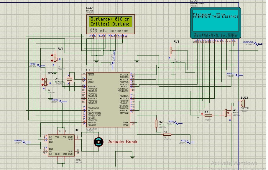 FIG.7. Result for critical distance for front and safe distance for rear
From FIG.8. we can conclude that if there is a vehicle in front of a car containing this collision avoidance system at a distance of 13 cm microcontroller will command LCD to Display “Actuator On” to the driver of the car and microcontroller will instruct motor driver to activate actuator, motor driver will send high current towards actuator which will cause actuator to turn on and this actuator will automatically press the brake of the car to stop. If there is a vehicle approaching from rear and if it’s distance is less than 19 cm micro controller will instruct GLCD to display the distance information along with the message of “TENT TO COLLISION’’ to the incoming car from the back.
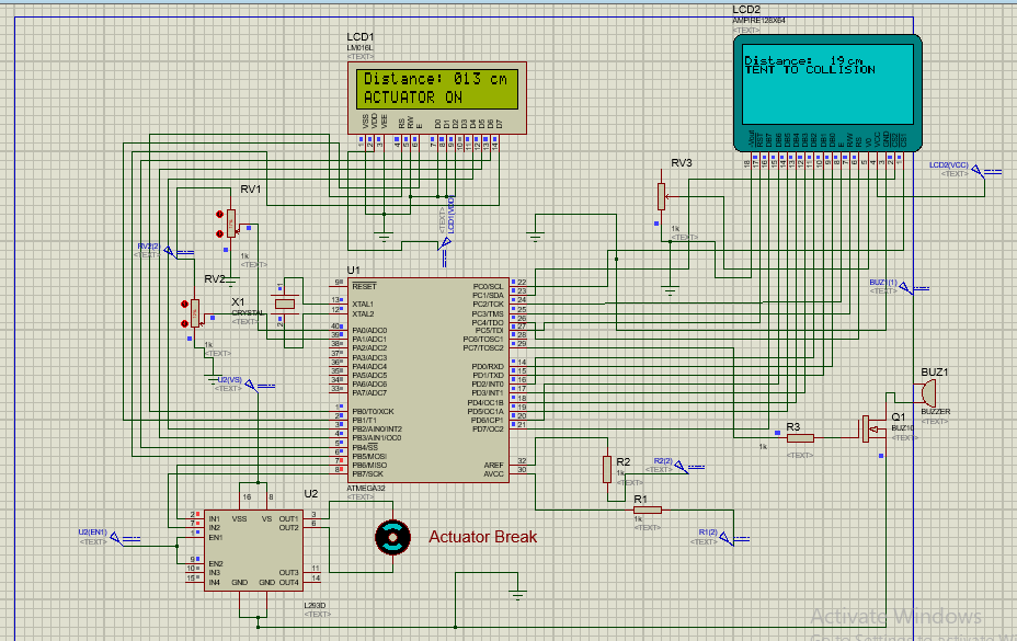 FIG.8. Result for Actuator On distance for front and tent to collision distance for rear
6. Result analysis:
During simulation distance was taken in small scale as in cm. For forward collision prevention system instruction for microcontroller was set in a way if measured distance by distance sensor is above 30 cm it will consider this distance to safe distance and it will instruct LCD to display to show the message safe distance along with that distance value. If the value of distance varies from 20 cm to 29 cm microcontroller will instruct LCD to show Close distance along with the value of the distance measured by the sharp distance sensor, further more microcontroller will send a pulsating signal to buzzer and buzzer will be turn on, this pulsating signal will cause change in the sound frequency of that buzzer. And if distance ranges from 15cm to 19 cm micro controller will instruct LCD to display the message “critical distance along with the measured distance “at the same time microcontroller will send a continuous signal to the buzzer and it will buzzed, this buzzing frequency will be different from the previous one. And any distance less than 15 cm microcontroller will instruct motor driver to turn on the actuation system to stop the car. At the same time LCD will display “Actuator on along with distance information”. From the simulated result, which were shown in the previous section; it is seen that when sharp distance sensors measure a distance of 35 cm LCD shows the message of safe distance which is larger than 30 cm. When measured distance by sensor was found 27 cm LCD shows the messages that this distance is close distance and at the same time a pulsating signal was sent to buzzer circuit. This measured distance was less than 29 cm. When distance was found about 18 cm LCD display message that this distance is critical distance, which was less than 20 cm. At the same time buzzer circuit will be turn on as micro controller sends a continuous signal to buzzer. From FIG.7 it can be seen that a red dot is appearing in front of the R3 resistor and which was connected with the microcontroller PC7 port and same red dot is appearing in that particular pin which indicates that microcontroller sending continuous signal to buzzer to buzz. Finally when distance was measured 13 cm which is less than 15 cm LCD displays the message that actuator on along with the measured value of distance in cm. From FIG.8 it is seen that there were two red dots in pin 2 and 7 of the motor driver which were connected to microcontroller pin 7 and pin 8 and same dots appear across those pins, which indicates microcontroller is sending high signal to motor driver to turn on the actuator or the motor of the actuator system. As motor driver needs high or low logic in its both pin to stop the motor of actuating signal and microcontroller is sending high signal to that motor driver is evidence that microcontroller is actually control the braking system of the vehicle and it will cause the car to stop.
For back collision avoidance system, the set of instruction for microcontroller was if measured distance is above 25cm it will be considered as a safe distance and GLCD will show “Maintain this distance” along with measured distance. Any distance less than 25 cm and greater 20 cm microcontroller will instruct GLCD to show “slowdown” along with measured distance value. Any distance ranges 19 cm to 15 cm microcontroller will instruct GLCD to display “tent to collision” along with the distance that was measured by sharp distance sensor. Finally any distance measured by the sharp distance sensor less than 15 cm microcontroller will instruct GLCD to display “Emergency! Stop”. FIG.5 to FIG.8 in the simulation and result section it’s seen that the measured distance by rear sharp distance sensor was 21cm, 12c m, 27 cm, 19 cm respectively, this distances follow the ranges that were mentioned above . And GLCD is displaying same sort of the message for that particular range of distances. From the above discussion it can be concluded that microcontroller is executing its instruction perfectly as it was given to it by a program which was written in MIKROC PRO for AVR, which results in that proposed design system is perfectly working during simulation. But when this system will be practically implemented for vehicle this distance range wouldn’t be applicable, virtually all vehicles’ or cars’ road braking performance test indicate stopping distances for 60 mph are typically 36m to43m [12]. So when this system will be implemented in reality only the set of instructions will need to be changed which will be loaded in microcontroller.
7. Implemented forward collision system
The design of the research work in this paper is the extended design of the implementation of “Automated Anti Collision System for Automobiles” [1] which has been implemented successfully in practical by prototype prior, where a Sharp distance sensor, microcontroller PIC16f876a, motor driver, linear actuator alarming device and LCD display were used. From following figures we will see the complete view of previously implemented prototype device along with its distance ranges.
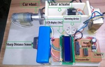 FIG.9: Implemented Prototype Device
From FIG.9.we can see the complete view of previously implemented prototype device.
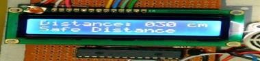 FIG.10. Safe distance of the prototype device
![]() FIG.11. Too close distance detected by prototype device
FIG.11. Too close distance detected by prototype device
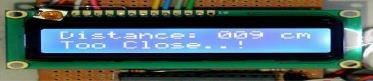 FIG.12. Critical close distance detected by prototype device
From FIG.10.we can see the distance is 30 cm which was considered as safe distance and the actuator did not work. In FIG.11.and FIG.12.we can see distances as follow 24 cm and 09 cm whereas, 21 cm gave alarm to the actuator and in 09 cm, and actuator started working. In addition, the research of this paper has been done with the back collision avoidance system along with this mentioned forward collision avoidance system. Also more progress has been done about the forward obstacles detection distance ranges. Due to shortage of time this recent extended research work prototype was not possible to implement.
8. Application and Improvement plan of the system
Proposed system which is described in this paper will be implemented by prototype practically very soon. Near future, during manufacture it can be implanted in motor bikes taxi-cab, car, and truck even in aircraft system. In winter when roads might be rarely seen due to fogs this system will notify the person who will be in control of that vehicle about other vehicles or any other obstacles ahead of his vehicle. Which will help him drive safely his vehicle, and it will make him feel comfortable while driving and it will also extinguish his fear. This will reduce terrifying collision of the vehicles and not only the winter, in other season it will notify driver to maintain a safe distance by alarming sound or showing distance information in LCD. If driver begin to avoid the alarming sound and start to drive recklessly system will forcefully stop the car to avoid accident. Researchers of this paper has some future improvement plan for making this system more convenient and add other features to make this system more accurate. For improving this system sonar system will be implemented due to its long range detection, Emergency light or special kind of alarm will be used to notify the vehicle to maintain safe distance, graphical symbols will be added along with messages in GLCD. Wireless Fidelity (Wi-Fi) technology can be used for transferring information between successive vehicle about the distance and what speed should the kept for safety, furthermore, Dual Infra-Red Obstacle Detector (DROD40) can be used in this system to determine obstacle in every side such as left, right and ahead distinctly. In future, researchers of this paper have plan to design a system which will monitor driver health condition to judge his fitness for driving if he isn’t fit, vehicle will not start. So, this will reduce almost 60% of accident.
Conclusion
Technologies, new inventions and transport system play an important role in human lives. Mankind is becoming habituated to these new inventions. Especially transport system without this mankind even think about their daily activities and even can step outside from their home. As every other invention this transport system has adverse effect too, and as usual mankind is responsible for this kind of adverse effect. People are always in rush to reach their destination as early as possible to save their time or to reach their destination on time without thinking about their lives value, what would happen if they met up with an accident which means colliding with other vehicle for their tendency to go somewhere within a flash. This results in injury or loses of their lives. The prime motive of the design is to reduce these accidents. In other words it can be concluded that this design is used to save human lives from the loss due to accident and also to ensure safe and comfortable journey.
Acknowledgment
First and foremost, we want to express our gratitude towards Almighty creator for his blessings without which it would not be possible to complete this work successfully afterwards want to acknowledge the constant support received from our family. It is an honor to express our heartiest gratitude to MS. Muhit, Assistant Professor, Faculty of Electrical and Electronic Engineering, AIUB, for his immense support and encouragement to improvise this designed system. And finally especial gratitude to honorable Mr. Chowdhury Akram Hossain, Assistant Professor, Faculty of Electrical and Electronic Engineering, AIUB. Without his motivation this work wouldn’t be possible to advance so far. Finally, any errors are our own and should not tarnish the reputations of these esteemed persons.
- Tasneem Sanjana, Kazi Ahmed AsifFuad, Mehrab Masayeed Habib, Ahmed Amin Rumel “Automated Anti-Collision System for Automobiles” in International Conference on Electrical, Computer and Communication Engineering (ECCE), Cox’s Bazar Bangladesh February 16-18, 2017 http://DOI: 1109/ECACE.2017.7913024
- http://www-nrd.nhtsa.dot.gov/pdf/esv/esv19/05-0322-O.pdf [Cited: 14 May, 2015]. Available:
- , Mechanisms and Mechanical Devices Source book 4th Edition (2007), 25, McGraw- Hill [Cited: 17 May 2015].
- http://www.microchip.com/wwwproducts/en/ATmega32 [Cited: 13 May, 2015]. Available:
- http://www.sharpsma.com/webfm_send/1208 [Cited: 17 May, 2015]. Available:
- Roboticlab website abailable at, http:// home. roboticlab.Eu/en/examples/sensor/ir_distance(Cited : 17, May 2016).
- https://www.firgelliauto.com/blogs/news/18090539-linear-actuator-how-to[Cited: 17 May, 2015]. Available:
- http://www.electronics-tutorials.ws/oscillator/crystal.html[Cited: 17 May, 2015]. Available
- http://www.engineersgarage.com/sites/default/files/L293D.pdfCited: 7 May 2015]. Available:
- http://www.engineersgarage.com/sites/default/files/LCD%2016×2.pdf [Cited: 17 May , 2015]. Available:
- https://www.electronify.org/basic-component-introduction/graphics-lcd [Cited: 17 May, 2015]. Available:
- Divya P.&MurugesanA.,”Intelligent Car Braking System with collisinAvoidance and ABS”,International Journal of Computer Applications(0975– 8887),National Conference on Information and Communication Technologies (NCICT , 2015).