
ARMA feeding techniques for isoflux coverage from a micro satellite
Volume 2, Issue 6, Page No 63-69, 2017
Author’s Name: Ali Siblini1,2 a), Hussein Abou Taam2, Bernard Jecko1, Mohammad Rammal2, Anthony Bellion3, Eric Arnaud1
View Affiliations
1Systems-RF University of Limoges, 12, rue Gemini 87068 Limoges Cedex 03, France
2Lebanese University, Doctoral School of Science and Technology, Beirut
3CNES, 18 Avenue Edouard Belin, 31401 Toulouse Cedex 9, France
a)Author to whom correspondence should be addressed. E-mail: ali.siblini.84@hotmail.com
Adv. Sci. Technol. Eng. Syst. J. 2(6), 49-55 (2017); ![]() DOI: 10.25046/aj020608
DOI: 10.25046/aj020608
Keywords: Agile Radiating, Matrix antenna, Multimode radiating beams, Spatial Telemetry

Export Citations
This paper deals with the design of a new reconfigurable beam antenna used to improve the efficiency of spatial telemetry links on Nano-Satellite. This agile beam antenna is not built on the well-known array concept AESA (Agile Electronically Scanned Array) but using a new one called ARMA (Agile Matrix Radiating Antenna); MARPEM in French. In this paper there is the design of the circularly polarized matrix antenna, the generation of two beam forming modes, the design of the distribution circuit and the polarization circuits.
Received: 26 September 2017, Accepted: 18 October 2017, Published Online: 04 November 2017
1. Introduction
The needs in high data rate of future Nano-satellite missions are incompatible with telemetry applications in VHF or S bands unlike the X-band. Moreover, most of applications require earth wide angle coverage in addition to a long time visibility, implying a theoretical isoflux radiation pattern particularly for LEO satellites. But this theoretical limited gain radiation pattern in nadir direction reduces the global efficiency of the PDTM (Payload Data Telemetry). A solution to maximize the PDTM is to use an agile beam antenna to increase the data rate efficiency by introducing several kinds of radiation patterns depending on the satellite position.
These links are produced by beams of various shapes delivered by an agile antenna working on several radiation modes. To limit the complexity of the architecture and to be accommodated on a Nano-satellite, these requirements lead to a dual mode circularly polarized antenna: one mode characterized by isoflux earth coverage and another one introducing high gain directive beam around the axial direction (nadir). To realize this PDTM link in X-band, a very compact antenna using dual mode radiation pattern has been developed with the following requirements:
- [8 – 8.4]GHz.
- To be accommodated on a 100mm x 100mm surface.
- Gain > 2dB for θ [-60°: 60°] and φ [-180°:180°].
- Axial Ratio < 4dB for θ [-60°:60°] and φ [-180°:180°].
The beam forming procedure and the switching process between two or more working modes need to use agile beam antennas. There are two kinds of electronically agile beam antennas; the first one is the well-known AESA (Agile Electronically Scanned Array) technique and the second, a new one, called ARMA (Agile Radiating Matrix Antenna) which introduces some advantages for such applications [1], [2] as larger angles beam scanning, higher power balance, side lobes minimization [3]-[6], lower couplings between adjacent elements and high gain solutions [7], [2] with smaller number of elements and less feeding network complexity.
In the context of this paper, the new ARMA concept is defined and the circularly polarized pixel with the polarization circuits design is presented. Then the ARMA matrix with circular polarization is used to generate two beams, the wide Isoflux and the high gain axial beams. Beam forming law is optimized to solve the problem of Isoflux dissymmetry in the different azimuthal planes,
2. The ARMA Concept
ARMA principle introduces new sampling procedure for the radiating surface of the antenna that is sampled or pixelated using the pixel. Brief comparison of AESA and ARMA principles is found in [3]. ARMA approach uses jointed pixels as shown in Figure 1 to sample the radiating surfaces instead a lot of punctual sources for the array technique [4]. Each pixel generates a uniform radiating surface that never overlaps outside its dimensions [3].
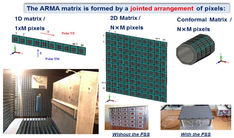 Figure 1. ARMA antennas architectures.
The most important point in ARMA approach is to be able to design a pixel which can generate a uniform EM field on its surface. This technique, deduced from the knowledge of EBG antennas properties, was extensively developed and validated in many papers [8]-[11] for linear polarization; it is the key point of the ARMA solution. Example of a pixel with one feeding probe is shown in Figure 2 with the corresponding radiating surface on the top.
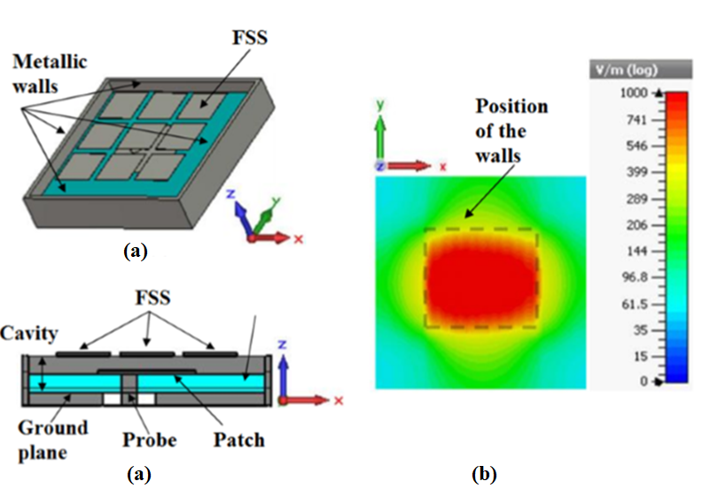 Figure 2. Pixel design: (a) FSS on top, patch inside the cavity and metallic walls, (b) the corresponding radiating surface.
For low profile antennas, a planar radiating surface S is built with pixels with a square radiating surfaces as shown in Figure 3.
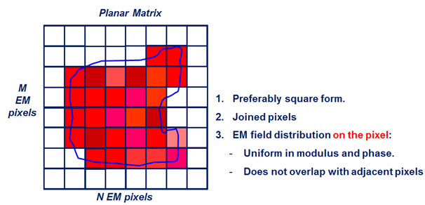 Figure 3. Radiating surface sampled by jointed square pixels.
3. Circularly Polarized Pixel Design
3.1. Pixel Design and Axial Ratio
For circular polarization (two orthogonal linear polarizations), the EBG cavity is usually fed by a patch probe generating a local circularly polarized field in the cavity. A good circular polarization can be obtained by two or four ports feeding circuit, shown in Figure 4. Of course, for a pixel considered alone, the axial ratio is better [12] [13] with the four ports technique (Figure 5 and Figure 6), but with higher manufacturing complexity and price.
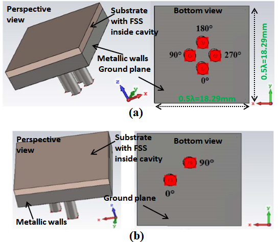 Figure 4. Pixel with two and four feeding ports for circular polarization generation.
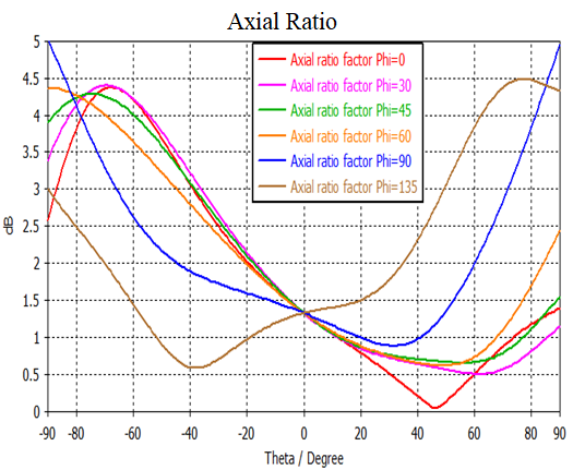 Figure 5. Axial ratio comparison obtained with a 2 ports ideal feeding procedure.
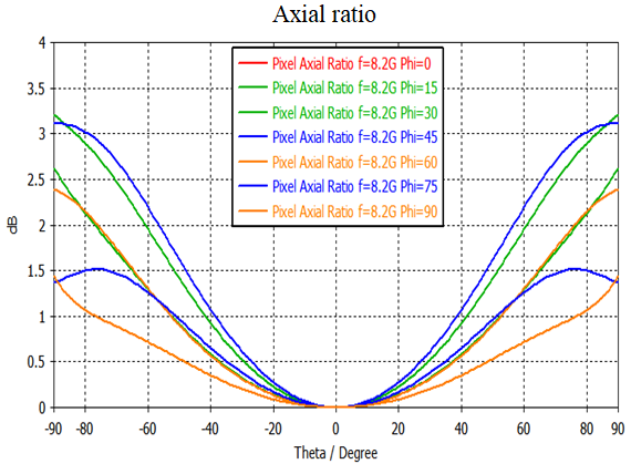 Figure 6. Axial ratio comparison obtained with a 4 ports ideal feeding procedure.
3.2. Polarization Circuits and Area Limitations
The main limitation in the design of the polarization circuit is the small area behind the pixel which is 18.29mmx18.29mm (0.5λx0.5) (Figure 4). This small area must include also the pad to solder the connector for the input power. For that the substrate TMM10i with permittivity 9.8 and thickness 0.381mm was used to print the circuit on it. The results of the axial ratio are not very modified by introducing the circuit to the pixel design: one hybrid coupler for the two ports case and 3 hybrid couplers for the 4 ports case as shown in Figure 7 and Figure 8.
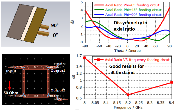 Figure 7. Axial ratios obtained with a one hybrid coupler for the two ports.
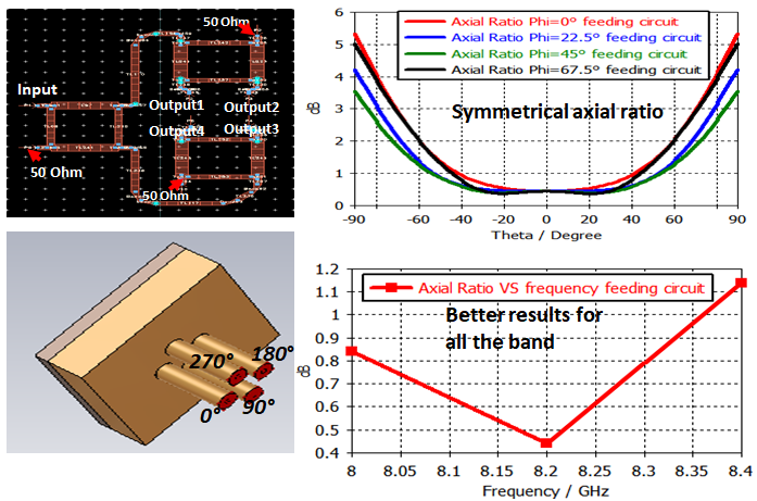 Figure 8. Axial ratios obtained with a d a 3 hybrid couplers for the 4 ports.
4. PDTM Application
4.1. Antenna Design
On this way, a square low profile ARMA antenna was built with 25 pixels where only nine are fed (Figure 9) by the BFN (Beam Forming Network); the other ones, located at the edges of the antenna, are only used to keep a good axial ratio for the whole matrix antenna.
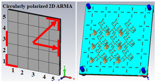 Figure 9. 25 pixels matrix antenna (left) with nine feeding ports and nine circular polarization circuits (Right).
4.2. Isoflux Pattern and Dissymmetry Problem
The isoflux coverage (first mode) is obtained by feeding the pixels with a weighting law deduced from a Sinc (sinus cardinal) function [14] [15]. This approach leads to weighting tables and to the corresponding matrix radiation patterns and axial ratios shown in Figure 10 and Figure 11.
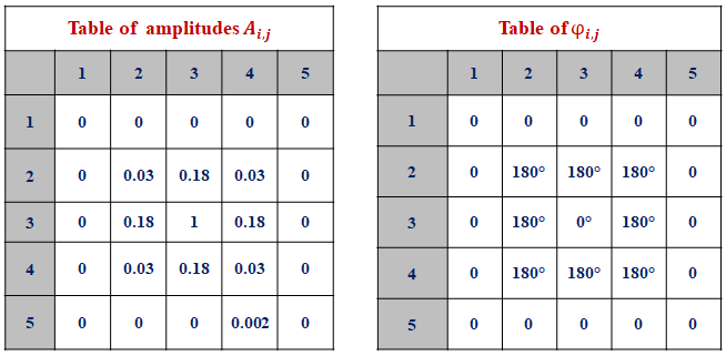 Figure 10. Sinc circular feeding law.
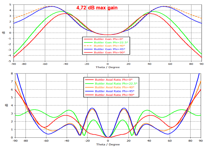 Figure 11. Gain an axial ratio patterns.
The pattern in Figure 11 shows a dissymmetry in the isoflux maximum gain positions (e.g. planes φ=0° and φ=45°); this is due to the non-symmetrical physical structure of the matrix antenna, where the distance from the center to the edges is not the same for all directions (Figure 9).
4.3. Feeding Law Optimization for Symmetrical isoflux
To compensate the dissymmetry resulted from the square matrix structure, the feeding law is optimized to modify the isoflux radiation pattern [15]. The value “A” is the weight applied on each pixel surrounding the central one, “A” is changed as shown in Figure 12, Figure 13 and Figure 14. This procedure, called Sinc-circular symmetrical, will be very useful to match easily the two modes together. It is also important to notice that the part of the following curves located between θ=±20° is not useful in the isoflux mode because for theses directions the matrix is working on the axial mode.
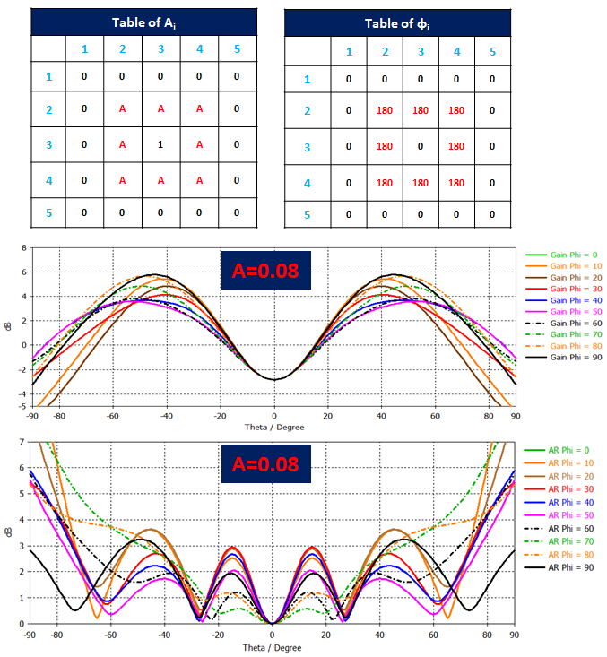 Figure 12. Gain and axial ratio evolution as a function of the elevation angle “θ” for different azimuth planes with A = 0.08.
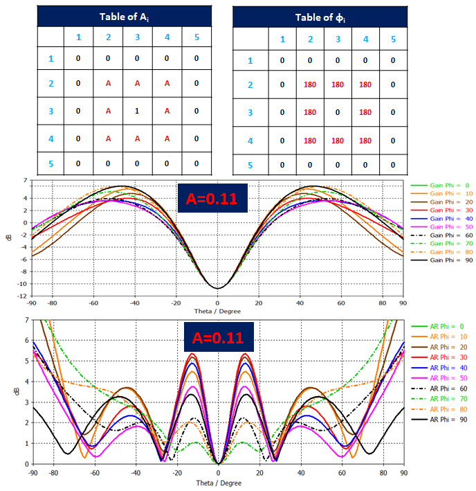 Figure 13. Gain and axial ratio evolution as a function of the elevation angle “θ” for different azimuth planes with A = 0.11.
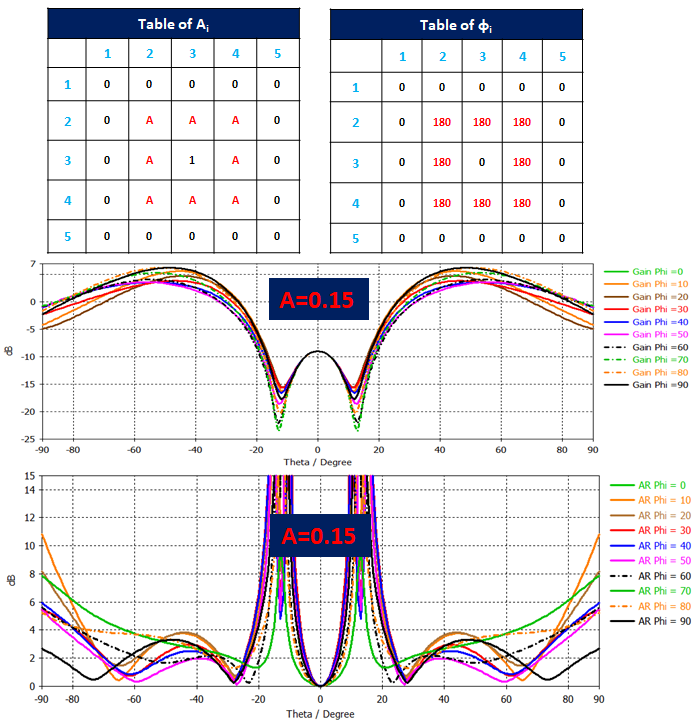 Figure 14. Gain and axial ratio evolution as a function of the elevation angle “θ” for different azimuth planes with A = 0.15.
Then with this symmetrical feeding solution the Isoflux gain pattern is more symmetrical with the position of the maximum gain located in the worst case at θ=±50° for the solution with A=0.15 (Figure 14). The axial ratio in this case is going very high for θ around ±20°, but these directions are not useful in this mode as mentioned above.
5. Directive Beam
The directive beam around the axial direction (second mode) is easy to obtain with the highest gain with all the weights equal to 1 (Figure 15). But, like for an array, it is also possible to optimize the radiation pattern and the axial ratio by modifying theses weights.
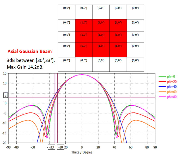 Figure 15. Radiation pattern of the axial mode as a function of the elevation angle θ for different azimuth planes φ.
6. Junction between Two Modes
The BFN (Beam Forming Network) architecture used to switch between the two modes is presented in Figure 16 for a 1D ARMA antenna.
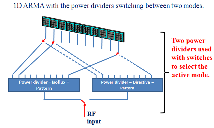 Figure 16. Switching procedure between the two modes.
The switching procedure [16] between the 2 modes can be easily performed for the elevation angle and the gain values expected by the users. For example it can be chosen to keep the gain above 3dB between -60° and +60° as shown in Figure 17.
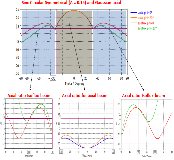 Figure 17. Two modes radiation patterns and axial ratios for the whole agile antenna for φ = 0° and φ = 20° planes.
7. Power Divider Design for Isoflux
The symmetrical feeding law with A=0.15 is considered for the Isoflux beam forming. To achieve this law a power divider was designed with one input and nine outputs as shown in Figure 18. The port labeled 5 is to be connected to the central pixel in the matrix antenna; the other output ports (1, 2, 3, 4, 6, 7, 8 and 9) will be connected to the other pixels around the central one. The return loss at the input of the power divider is shown in Figure 19. Using of the hybrid couplers at the outputs insure good matching (50Ω) when connecting the power divider to the polarization circuits that feed the patches inside the pixels cavities.
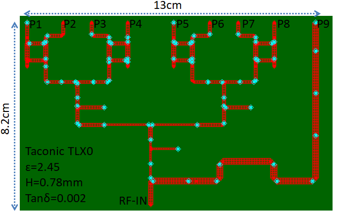 Figure 18. Power divider Momentum design for Isoflux beam forming.
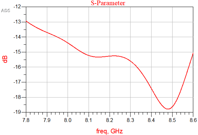 Figure 19. Return loss at the input of the power divider.
The output weights in magnitude and phase at 8.2GHz is presented in the table of Figure 20. These magnitudes are taken normalized with respect to the central port5 and the phases are the phase shift with the phase of port 5.
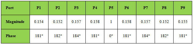 Figure 20. Outputs of the power divider at 8.2GHz.
8. Pattern of the Whole Matrix
Polarization circuits and the power divider results files are taken from Momentum software and connected to the matrix antenna in CST (Figure 21). The realized gain and the axial ratio patterns are shown in Figure 22 at 8.2GHz. The position of the isoflux maximum is attained at approximately at fixed elevation angles and the difference in the gain between the different azimuth planes is 2.9dB.
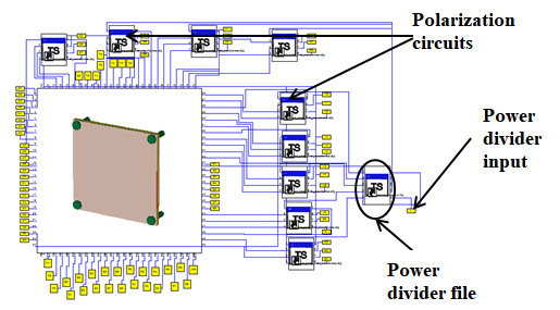 Figure 21. Matrix antenna with the polarization circuits and power divider.
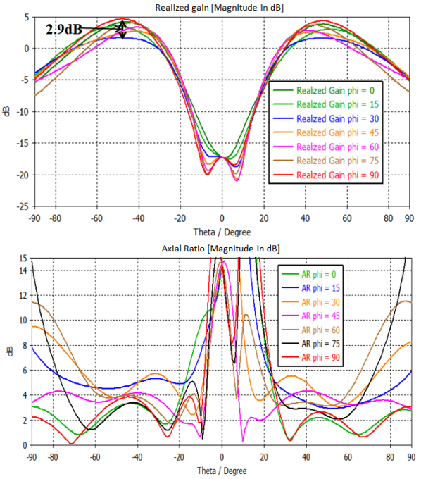 Figure 22. Realized gain and axial ratio patterns at 8.2GHz (whole antenna).
9. Testing the Antenna with the Nano-Satellite Support
The antenna is placed on the top of the Nano-satellite, so to check the effect of the satellite support the antenna was placed on the top of a metallic cube in CST (Figure 23) (cube with 130mm height and 100mm surface). In this case the antenna is tested as the real case for the satellite to be placed on it. Results of the antenna with and without the cube support show no significant modifications in the gain and axial ratio patterns (Figure 24).
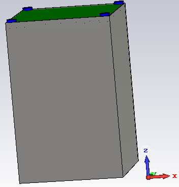 Figure 23. Antenna placed on the cube-sat support.
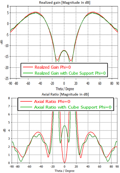 Figure 24. Realized gain and axial ratio patterns with and without cube-sat support.
10. Conclusion
A dual mode agile antenna based on the ARMA principle [1] [2] was presented in this paper. A prototype is under manufacturing and will be tested next month. The pixel with four ports with insures high stability of the axial ratio over wide elevation angles using the polarization circuit build by hybrid couplers. This pixel also insures the uniformity characteristics that are the basis of the new ARMA sampling procedure. The matrix ARMA was used to generate two different beams with and axial ratio for both below 3dB in their interesting regions. Also the antenna is tested on the Nano-satellite support with no problems.
Conflict of Interest
The authors declare no conflict of interest.
Acknowledgment
This work has been funded by the French Spatial Agency (CNES).
- Patent: JECKO, B.; HAJJ, M.; CHANTALAT, R.; SALAH TOUBET, «Antenne élémentaire et antenne réseau mono ou bidimensionnelle correspondante» PCT Patent: PCT/EP2012/076509; French Patent: FR 11 62141.
- ABOU TAAM, H., ZAKKA EL NASHEF, G., SALAH TOUBET, M., et al. Scan performance and re-configurability of agile radiating matrix antenna prototype. International Journal of Antennas and Propagation, 2015, vol. 2015.
- ABOU TAAM, Hussein, SALAH TOUBET, Moustapha, MONEDIERE, Thierry, et al. A new agile radiating system called electromagnetic band gap matrix antenna. International Journal of Antennas and Propagation, 2014, vol. 2014.
- TAAM, Hussein Abou, EL NASHEF, Georges Zakka, ARNAUD, Eric, et al. Design development and experimental validation of an EBG matrix antenna for tracking application. International Journal of Microwave and Wireless Technologies, 2015, p. 1-9.
- TAAM, Hussein Abou, NASHEF, El, ZAKKA, Georges, et al. Feeding technique for the experimental validation of EBG matrix antenna. Microwave and Optical Technology Letters, 2015, vol. 57, no 3, p. 533-537.
- TAAM, Hussein Abou, TOUBET, Moutapha Salah, MONEDIERE, Thierry, et al. Interests of a 1D EBG Matrix compared to a patch array in terms of mutual coupling and grating lobe. In: Antennas and Propagation (EuCAP), 2013 7th European Conference on. IEEE, 2013. p. 1045-1048.
- TAAM, Hussein Abou, TOUBET, Moutapha Salah, MONEDIERE, Thierry, et al. Radiation control of an agile Matrix antenna by using specific algorithm. In: Microwave Symposium (MMS), 2013 13th Mediterranean. IEEE, 2013. p. 1-4.
- TAAM, Hussein Abou, EL NASHEF, Georges Zakka, JECKO, Bernard, et al. Agile radiating matrix antenna system for radar applications. In : Radar Conference (Radar), 2014 International. IEEE, 2014. p. 1-4.
- TAAM, Hussein Abou, SIBLINI, Ali, EL NASHEF, Georges Zakka, et al. An agile electronically scanned EBG matrix antenna for monitoring target activity. In: Microwave Conference (EuMC), 2015 European. IEEE, 2015. p. 1435-1438.
- TAAM, H. Abou, EL NASHEF, G. Zakka, ARNAUD, E., et al. Experimental validation of an agile electromagnetic band gap matrix antenna. In: Antennas and Propagation (EuCAP), 2015 9th European Conference on. IEEE, 2015. p. 1-4.
- Jecko, E. Aranud, H. Abou Taam, A. Siblini The ARMA concept: Comparison of AESA and ARMA technologies for agile antenna design. Fermat Journal vol.20, 2016
- SIBLINI, Ali, TAAM, Hussein Abou, JECKO, Bernard, Rammal, Mohammad. Pixel and Patch Comparison. SENSET 2017 Sensors, Networks, Smart and Emerging Technologies, Beirut Lebanon.
- SIBLINI, Ali, TAAM, Hussein Abou, JECKO, Bernard, et al. Wideband circularly polarized pixel antenna using special EBG approach: Building of agile antenna ARMA for space applications. In: Antennas and Propagation (MECAP), 2016 IEEE Middle East Conference on. IEEE, 2016. p. 1-4.
- SIBLINI, Ali, TAAM, Hussein Abou, JECKO, Bernard, Rammal, Mohammad. Pixel and Patch Comparison. New Circularly Polarized Matrix Antenna for Space Applications. Wireless testing symposiums 2016 London.
- SIBLINI, Ali, TAAM, Hussein Abou, JECKO, Bernard, et al. New agile EBG matrix antenna for space applications. In: Microwave Conference (EuMC), 2016 46th European. IEEE, 2016. p. 874-877.
- SIBLINI, Ali, JECKO, Bernard, et ARNAUD, Eric. Multimode reconfigurable Nano-satellite antenna for PDTM application. In: Antennas and Propagation (EUCAP), 2017 11th European Conference on. IEEE, 2017. p. 542-545.